
Page 190 - Build Your Own Quadcopter_ Power Up Your Designs with the Parallax Elev-8
P. 190
Chapter 7: Ser v o Motors and Extending the Ser v o Control System 169
Figure 7.11 Mechanical stop.
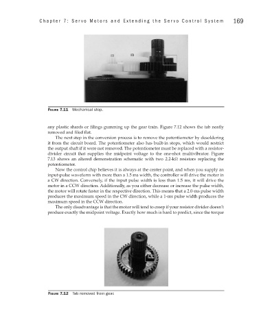
any plastic shards or filings gumming up the gear train. Figure 7.12 shows the tab neatly
removed and filed flat.
The next step in the conversion process is to remove the potentiometer by desoldering
it from the circuit board. The potentiometer also has built-in stops, which would restrict
the output shaft if it were not removed. The potentiometer must be replaced with a resistor-
divider circuit that supplies the midpoint voltage to the one-shot multivibrator. Figure
7.13 shows an altered demonstration schematic with two 2.2-kΩ resistors replacing the
potentiometer.
Now the control chip believes it is always at the center point, and when you supply an
input-pulse waveform with more than a 1.5 ms width, the controller will drive the motor in
a CW direction. Conversely, if the input pulse width is less than 1.5 ms, it will drive the
motor in a CCW direction. Additionally, as you either decrease or increase the pulse width,
the motor will rotate faster in the respective direction. This means that a 2.0-ms pulse width
produces the maximum speed in the CW direction, while a 1-ms pulse width produces the
maximum speed in the CCW direction.
The only disadvantage is that the motor will tend to creep if your resistor divider doesn’t
produce exactly the midpoint voltage. Exactly how much is hard to predict, since the torque
Figure 7.12 Tab removed from gear.