
Page 187 - Build Your Own Quadcopter_ Power Up Your Designs with the Parallax Elev-8
P. 187
166 Bu il d Y o ur O w n Q u a d c o p t e r
The above analysis, while a bit lengthy and detailed, was provided to give you an
understanding of the complexity of what is constantly happening within the servo case. This
knowledge should help you determine what might be happening if one of your servos starts
operating in an erratic manner.
The word deadband, as mentioned in step 4 of the analysis, is worth further explanation.
Deadband used in this context refers to a slight voltage change in the control input that
should not elicit an output. This is a deliberate design feature created for the instance when
you do not want the servo to react to any slight input changes. Using a deadband improves
servo life and makes it less jittery during normal operations. The deadband is fixed in the
demonstration circuit by a 1 kΩ-resistor connected between pins 9 and 11. This resistor forms
another feedback loop between the pulse-stretcher input and output.
The last servo parameter I will discuss is the pulse-stretcher gain, which largely controls
the error pulse length. This gain in the demonstration circuit is set by the values of the
capacitor from pin 11 to ground and the resistor connected between pins 11 and 13. This gain
would also be referred to as the proportional gain (K ) in closed-loop control theory. It is
p
important to have the gain set to what is sometimes jokingly called the “Goldie Locks
region,” not too high and not too low, but just right. Too much gain makes the servo much
too sensitive and possibly could lead to unstable oscillations. Too little gain makes it too
insensitive and prone to very poor response. Sometimes, experimenters will tweak the
resistor and capacitor values in an effort to squeeze out a bit more performance from a servo;
however, I believe the manufacturers have already set the component values for a good
compromise between performance and stability.
The Digital Servo
It turns out that there are almost no differences between analog and digital mechanical servo
components. The mechanical differences, when present, are often related to using metal
gears and ball bearings in digital units, which are more expensive than the analog units.
However, the main difference is found in the electronic-control board. The analog control
was explained in the previous section: analog-control circuits are used in conjunction with
digital-logic and comparator circuits. No numeric calculations or analog-to-digital conversions
(ADC) are done in an analog servo; hence, there is no need for the microcontroller chip that
is present in the digital servo.
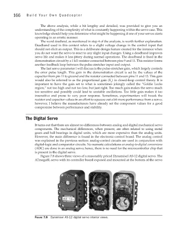
Figure 7.8 shows three views of a reasonably priced Dynamixel AS-12 digital servo. The
ATmega8L servo with its controller board exposed and mounted at the bottom of the servo
Figure 7.8 Dynamixel AS-12 digital servo interior views.