
Page 191 - Build Your Own Quadcopter_ Power Up Your Designs with the Parallax Elev-8
P. 191
170 Bu il d Y o ur O w n Q u a d c o p t e r
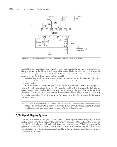
Figure 7.13 Demonstration M51660L schematic altered for CR operation.
needed to meet operational requirements plays a part in actually moving whatever object is
being powered by the CR servos. A large robot would likely not even move because of the
minute creep signal that is created. I would definitely use matched or precision resistors in
order to divide the voltage as precisely as possible.
Another way to address this issue is to alter the value of the deadband resistor (the 1 kΩ)
to help eliminate the undesired motion. It would take a trial-and-error process to determine
the correct value.
There is one final caveat that you should know. It is entirely possible that the plus or
minus .5-ms deviation from the center 1.5-ms pulse width will not produce the full rotation
speed change that is possible. This is entirely due to having too large a value for the feedback
resister R . The value set for this resistor in the demonstration circuit is 560 kΩ. This may
f
have to be lowered to 120 kΩ to achieve the full speed capability for pulse widths that range
from 1 to 2 ms.
Note: This conversion process of changing standard servos to CR servos is applicable only to analog
servos. I am not aware of any process to convert a digital servo. It may be possible but certainly
would involve changing proprietary firmware, which is just not feasible.
R/C Signal Display System
It is critical to confirm the quality and values of pulse signals when designing a control
system based upon those signals. The following system uses a BOE and an LCD to display
three R/C channel pulse widths in real time. I used an ordinary 9-V battery to power the
system in order to show that it has minimal power requirements. Figure 7.14 shows a
pictorial diagram of the main components and how they are interconnected using standard
three-wire servo cables.