
Page 193 - Build Your Own Quadcopter_ Power Up Your Designs with the Parallax Elev-8
P. 193
172 Bu il d Y o ur O w n Q u a d c o p t e r
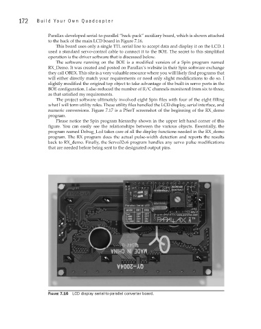
Parallax-developed serial-to-parallel “back-pack” auxiliary board, which is shown attached
to the back of the main LCD board in Figure 7.16.
This board uses only a single TTL serial line to accept data and display it on the LCD. I
used a standard servo-control cable to connect it to the BOE. The secret to this simplified
operation is the driver software that is discussed below.
The software running on the BOE is a modified version of a Spin program named
RX_Demo. It was created and posted on Parallax’s website in their Spin software exchange
they call OBEX. This site is a very valuable resource where you will likely find programs that
will either directly match your requirements or need only slight modifications to do so. I
slightly modified the original top object to take advantage of the built-in servo ports in the
BOE configuration. I also reduced the number of R/C channels monitored from six to three,
as that satisfied my requirements.
The project software ultimately involved eight Spin files with four of the eight filling
what I will term utility roles. These utility files handled the LCD display, serial interface, and
numeric conversions. Figure 7.17 is a PSerT screenshot of the beginning of the RX_demo
program.
Please notice the Spin program hierarchy shown in the upper left-hand corner of this
figure. You can easily see the relationships between the various objects. Essentially, the
program named Debug_Lcd takes care of all the display functions needed in the RX_demo
program. The RX program does the actual pulse-width detection and reports the results
back to RX_demo. Finally, the Servo32v6 program handles any servo pulse modifications
that are needed before being sent to the designated output pins.
Figure 7.16 LCD display serial-to-parallel converter board.