
Page 196 - Build Your Own Quadcopter_ Power Up Your Designs with the Parallax Elev-8
P. 196
Chapter 7: Ser v o Motors and Extending the Ser v o Control System 175
waitcnt(clkfreq/2 + cnt) ‘wait .5 seconds
repeat
repeat i from 0 to 2
pulse[i] := pulsewidth[i] ‘capture pulse values from
pins 14 to 16
waitcnt(clkfreq / 2 + cnt)
updateLCD(pulse[0],pulse[1],pulse[2]) ‘display pulse values on
LCD
out(i, pulse[i]) ‘send servo pulses out
2
PRI updateLCD(value1, value2, value3) | numstr
numstr := num.dec(value1)
lcd.str(numstr)
lcd.str(string(“ “))
numstr := num.dec(value2)
lcd.str(numstr)
lcd.str(string(“ “))
numstr := num.dec(value3)
lcd.str(numstr)
lcd.str(string(13))
PUB out(_pin, _pulse)
servo.set(_pin, _pulse)
DAT
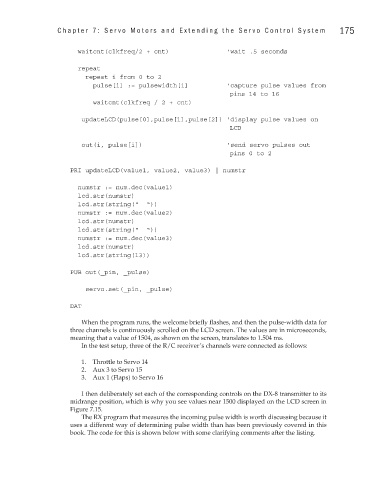
When the program runs, the welcome briefly flashes, and then the pulse-width data for
three channels is continuously scrolled on the LCD screen. The values are in microseconds,
meaning that a value of 1504, as shown on the screen, translates to 1.504 ms.
In the test setup, three of the R/C receiver’s channels were connected as follows:
1. Throttle to Servo 14
2. Aux 3 to Servo 15
3. Aux 1 (Flaps) to Servo 16
I then deliberately set each of the corresponding controls on the DX-8 transmitter to its
midrange position, which is why you see values near 1500 displayed on the LCD screen in
Figure 7.15.
The RX program that measures the incoming pulse width is worth discussing because it
uses a different way of determining pulse width than has been previously covered in this
book. The code for this is shown below with some clarifying comments after the listing.