
Page 192 - Build Your Own Quadcopter_ Power Up Your Designs with the Parallax Elev-8
P. 192
Chapter 7: Ser v o Motors and Extending the Ser v o Control System 171
Figure 7.14 Pictorial diagram of the real-time, servo-pulse-monitoring test system.
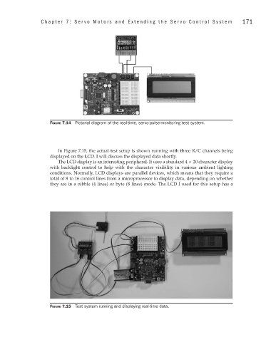
In Figure 7.15, the actual test setup is shown running with three R/C channels being
displayed on the LCD. I will discuss the displayed data shortly.
The LCD display is an interesting peripheral. It uses a standard 4 × 20 character display
with backlight control to help with the character visibility in various ambient lighting
conditions. Normally, LCD displays are parallel devices, which means that they require a
total of 8 to 16 control lines from a microprocessor to display data, depending on whether
they are in a nibble (4 lines) or byte (8 lines) mode. The LCD I used for this setup has a
Figure 7.15 Test system running and displaying real-time data.