
Page 189 - Build Your Own Quadcopter_ Power Up Your Designs with the Parallax Elev-8
P. 189
168 Bu il d Y o ur O w n Q u a d c o p t e r
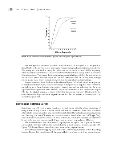
Figure 7.10 Deadband characteristic graphs for analog and digital servos.
The analog servo is referred to as the “Standard Servo” in the figure. Also, Diagrams 1,
2, and 3 refer to the no-power, low-power, and high-power operating conditions, respectively.
The analog servo is fixed at using the pulses that arrive at the nominal 50-Hz frequency,
while the digital servo creates as many as six times that number of analog pulses in the same
20-ms time frame. This means that more average power is being applied to the internal servo
motor, which results in more torque and a much faster response. Of course, more average
power means more power consumption, which is the digital servo disadvantage.
One more excerpt from the Futaba datasheet is Figure 7.10, which shows a comparison
of deadband characteristics, such as percentage of torque versus response time. What you
are looking for in these characteristic graphs is a nearly vertical line indicating that the servo
rapidly builds torque to the 100% level in a very short time interval. You can see from Figure
7.10 that the digital response is much better than the analog response. This is due to the
controller continuing to optimize its performance and the much faster update rate that is in
use in the digital unit.
Continuous Rotation Servos
Sometimes you will need a servo to act as a normal motor with the added advantage of
being able to closely control both the speed and rotation direction. I have used continuous
rotation (CR) servos for quite a long time in the robots I build for both classroom and personal
use. You may purchase CR servos, or you can convert a standard servo to a CR type fairly
easily. CR servos are almost identical in price to standard servos. I will explain the difference
between the two, and you can decide if you want to convert or purchase a CR servo.
The standard servo has a mechanical stop in place on a gear that is part of the main
output shaft. This tab restricts the output shaft to a fixed range of motion, usually 180°.
Figure 7.11 shows this mechanical stop on a standard servo gear train set.
I would recommend snapping the tab off with a sharp diagonal cutter rather than filing
it down. Ensure that you disassemble the gear set before working on it, since you don’t want