
Page 184 - Build Your Own Quadcopter_ Power Up Your Designs with the Parallax Elev-8
P. 184
Chapter 7: Ser v o Motors and Extending the Ser v o Control System 163
Figure 7.3 Servo horns.
I will tell you more about the potentiometer’s function during the control-board
discussion. For now, I will simply state that it forms part of a closed-loop control system that
I introduced in Chapter 2. If you skipped that part, it might be a good time to go back and
review the topic, as it applies to this case.
The servo horn is simply a plastic part that slips into grooves at the end of the output
shaft and is used as part of a mechanical actuating mechanism. It is held in place with a very
small machine screw. The shaft grooves ensure that the horn does not slip under load. Figure
7.3 shows a close-up of some typical servo horns.
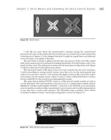
The electronics board is the heart of the servo and controls how the servo functions.
I will be describing an analog-control version, since that is, by far, the most popular type
used in low-cost servo motors. I will mention the digital version at the end of this section
and compare it to the analog version. Figure 7.4 shows a Hitec control board that is in place
for the model HS-311 that I used for my demonstration system.
The main chip is labeled HT7002, which is a Hitec private model number as well as
I could determine. This chip functions in the same way as a commercially available chip by
Mitsubishi with the model number M51660L. I will refer to the M51660L in my discussion,
since it is used in a number of other manufacturer’s servo motors and would be representative
of any chip that is used in this situation. The Mitsubishi chip is entitled “Servo Motor
Controller for Radio Control,” and its pin configuration is shown in Figure 7.5.
Figure 7.4 Hitec HS-311 electronics board.