
Page 180 - Build Your Own Quadcopter_ Power Up Your Designs with the Parallax Elev-8
P. 180
Chapter 6: Radio-Controlled Systems and Telemetr y 159
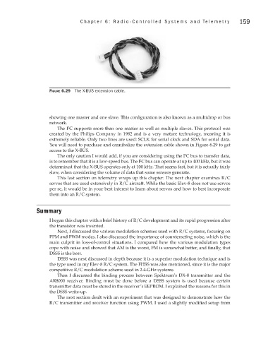
Figure 6.29 The X-BUS extension cable.
showing one master and one slave. This configuration is also known as a multidrop or bus
network.
2
The I C supports more than one master as well as multiple slaves. This protocol was
created by the Philips Company in 1982 and is a very mature technology, meaning it is
extremely reliable. Only two lines are used: SCLK for serial clock and SDA for serial data.
You will need to purchase and cannibalize the extension cable shown in Figure 6.29 to get
access to the X-BUS.
The only caution I would add, if you are considering using the I C bus to transfer data,
2
2
is to remember that it is a low-speed bus. The I C bus can operate at up to 400 kHz, but it was
determined that the X-BUS operates only at 100 kHz. That seems fast, but it is actually fairly
slow, when considering the volume of data that some sensors generate.
This last section on telemetry wraps up this chapter. The next chapter examines R/C
servos that are used extensively in R/C aircraft. While the basic Elev-8 does not use servos
per se, it would be in your best interest to learn about servos and how to best incorporate
them into an R/C system.
Summary
I began this chapter with a brief history of R/C development and its rapid progression after
the transistor was invented.
Next, I discussed the various modulation schemes used with R/C systems, focusing on
PPM and PWM modes. I also discussed the importance of counteracting noise, which is the
main culprit in loss-of-control situations. I compared how the various modulation types
cope with noise and showed that AM is the worst, FM is somewhat better, and finally, that
DSSS is the best.
DSSS was next discussed in depth because it is a superior modulation technique and is
the type used in my Elev-8 R/C system. The FHSS was also mentioned, since it is the major
competitive R/C modulation scheme used in 2.4-GHz systems.
Then I discussed the binding process between Spektrum’s DX-8 transmitter and the
AR8000 receiver. Binding must be done before a DSSS system is used because certain
transmitter data must be stored in the receiver’s EEPROM. I explained the reasons for this in
the DSSS write-up.
The next section dealt with an experiment that was designed to demonstrate how the
R/C transmitter and receiver function using PWM. I used a slightly modified setup from