
Page 207 - Build Your Own Quadcopter_ Power Up Your Designs with the Parallax Elev-8
P. 207
186 Bu il d Y o ur O w n Q u a d c o p t e r
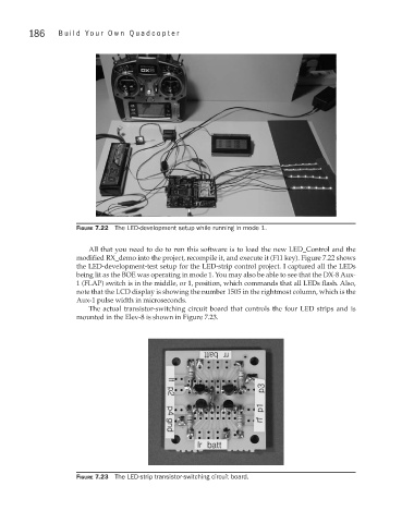
Figure 7.22 The LED-development setup while running in mode 1.
All that you need to do to run this software is to load the new LED_Control and the
modified RX_demo into the project, recompile it, and execute it (F11 key). Figure 7.22 shows
the LED-development-test setup for the LED-strip control project. I captured all the LEDs
being lit as the BOE was operating in mode 1. You may also be able to see that the DX-8 Aux-
1 (FLAP) switch is in the middle, or 1, position, which commands that all LEDs flash. Also,
note that the LCD display is showing the number 1505 in the rightmost column, which is the
Aux-1 pulse width in microseconds.
The actual transistor-switching circuit board that controls the four LED strips and is
mounted in the Elev-8 is shown in Figure 7.23.
Figure 7.23 The LED-strip transistor-switching circuit board.