
Page 208 - Build Your Own Quadcopter_ Power Up Your Designs with the Parallax Elev-8
P. 208
Chapter 7: Ser v o Motors and Extending the Ser v o Control System 187
Figure 7.24 Installation of the LED-strip transistor-switching circuit board.
The complete transistor-switching board may be installed between the Elev-8 boom
ends, as shown in Figure 7.24. I have also wired all the LED-strip power leads to the
transistor-switching circuit board in this figure.
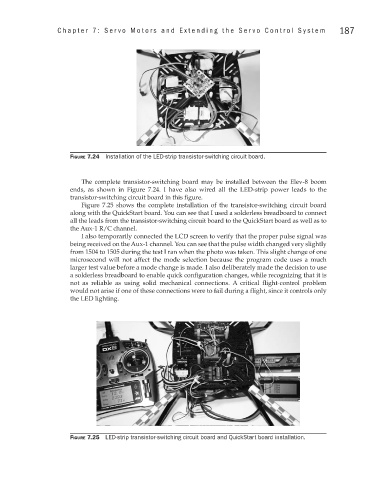
Figure 7.25 shows the complete installation of the transistor-switching circuit board
along with the QuickStart board. You can see that I used a solderless breadboard to connect
all the leads from the transistor-switching circuit board to the QuickStart board as well as to
the Aux-1 R/C channel.
I also temporarily connected the LCD screen to verify that the proper pulse signal was
being received on the Aux-1 channel. You can see that the pulse width changed very slightly
from 1504 to 1505 during the test I ran when the photo was taken. This slight change of one
microsecond will not affect the mode selection because the program code uses a much
larger test value before a mode change is made. I also deliberately made the decision to use
a solderless breadboard to enable quick configuration changes, while recognizing that it is
not as reliable as using solid mechanical connections. A critical flight-control problem
would not arise if one of these connections were to fail during a flight, since it controls only
the LED lighting.
Figure 7.25 LED-strip transistor-switching circuit board and QuickStart board installation.