
Page 119 - Build Your Own Transistor Radios a Hobbyists Guide to High-Performance and Low-Powered Radio Circuits
P. 119
frequency (e.g., 455 kHz) is done with an IF amplifier, and the output of the IF
amplifier is connected to a second IF filter.
From the second IF filter comes a 4S5-kHz AM signal, which is demodulated by an
envelope detector (or power detector). The envelope detector performs half-wave
rectification on the negative half (lower half) of the AM envelope for two functions.
One function is to provide a demodulated AM signal or an audio signal. The second
function is to provide a negative direct-current (DC) voltage for automatic volume
control (AVC). The negative DC voltage is level shifted up by adding a positive bias
voltage such that when a strong signal is received, the net total voltage is a positive
voltage that decreases in proportion to signal strength. And when a weak signal is
received, the net total voltage is still positive and increases in proportion to the
weakness of the received signal.
The DC bias voltage and the half-wave-rectified negative half of the AM envelope
are passed through a low-pass filter to remove IF and audio signals, passing only a
DC voltage to change the gain of the IF amplifier. For example, for a strong signal
received, the constant DC voltage is + 1.0 V, and when a weak signal is received,
the constant DC voltage is + 1.2 V. The AVC system allows a more even audio
volume between weak and strong stations received.
To raise the level of the demodulated AM signal, an audio amplifier (AF Amp) is
used to supply sufficient signal to drive a loudspeaker or low-impedance earphone ..
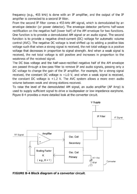
Figure 8-4 provides a more detailed look at the converter circuit.
V Supply
T
IF Filter
IF Signal
~er
RF Signal
Osc. Coil
~ " Secondary
/
/ r---
Scaling Factor
Osc. Coil
l/
'---- K
I" Primary VC1 Dsc
( e.g., K < 1 ) "i ~
60 pf Converter
n J
FIGURE 8-4 Block diagram of a converter circuit.