Page 118 - Build Your Own Transistor Radios a Hobbyists Guide to High-Performance and Low-Powered Radio Circuits
P. 118

f S 5
                                                                2nd Oet,Ave, AF Amp

                                                                                   0.


                                                3M  .
                                       J

                                               x                   ,

                                                L~;-l~ 67.?


                                                       M -lA '        BL -M 145
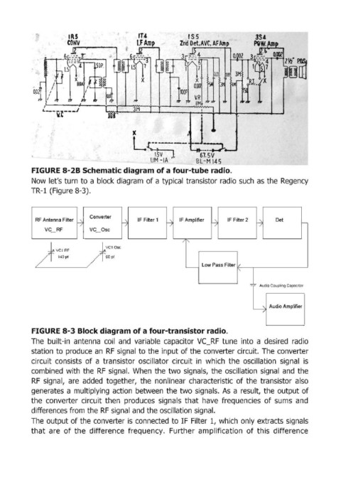
            FI GURE 8-2B Schematic diagram of a four-tube radio.
            Now  let's turn to a block diagram  of a typical  transistor radio  such  as  the  Regency
            TR-l (Figure 8-3).


                                Converter
             RF Antenna Filter                   IF Filter 1    IF Amplifier     IF Filter 2      Det
                            -7              ~               ~              ~               ~               t-
                                             /
                                                                                            /
                                                             /
                                                                            /
                 VC  RF         VC  Osc
                                                                 /   I"
                  +VC1RF            +VClOS'
             /       140pf     /      60 pt
                                                                        Low Pass Filter 1/
                                                                  ~
                                                                                    I'
                                                                                         =~ Audio Couplfng Capacitor


                                                                                               Audio Amplifier
                                                                                          ~
                                                                                             /

            FIGURE 8-3 Block diagram of a four-transistor radio.
            The  built-in  antenna  coil  and  variable  capaCitor  VC_RF  tune  into  a  desired  radio
            station  to produce  an  RF  signal to the  input of the converter circuit.  The converter
            circuit  consists  of a  transistor  oscillator  circuit  in  which  the  oscillation  signal  is

            combined  with  the RF  signal.  When  the  two  signals,  the  oscillation  signal and  the
            RF  signal,  are  added  together,  the  nonlinear  characteristic  of the  transistor  also
            generates  a multiplying  action  between  the  two signals.  As  a result,  the output  of
            the  converter  circuit  then  produces  signals that  have  frequencies  of sums  and
            differences from the RF signal and the oscillation  signal.

            The  output of the converter is connected  to IF Filter 1,  which  only extracts signals
            that  are  of the  difference  frequency.  Further  amplification  of this  difference
   113   114   115   116   117   118   119   120   121   122   123