
Page 116 - Build Your Own Transistor Radios a Hobbyists Guide to High-Performance and Low-Powered Radio Circuits
P. 116
RF Antenna Filter
e-
VC_ RF
'\/
)!. VC1 RF
....
/ 140 pt Frequency Translator IF Amplifier ~ Det Audio Amplifier
Mixer ~ / ~
/"-
Local Oscillator
f---
VC_ Osc
~VC1 Dsc
/ ..... 60 pr
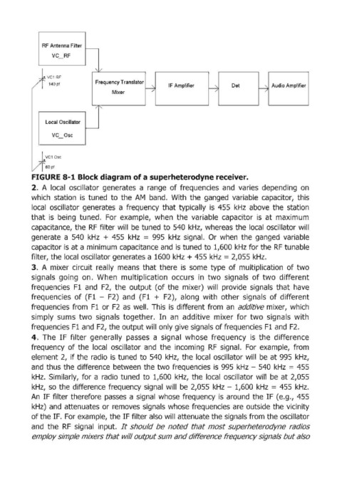
FIGURE 8-1 Block diagram of a superheterodyne receiver.
2. A local oscillator generates a range of frequencies and varies depending on
which station is tuned to the AM band. With the ganged variable capacitor, this
local oscillator generates a frequency that typically is 455 kHz above the station
that is being tuned. For example, when the variable capacitor is at maximum
capacitance, the RF filter will be tuned to 540 kHz, whereas the local oscillator will
generate a 540 kHz + 455 kHz = 995 kHz signal. Or when the ganged variable
capacitor is at a minimum, capacitance and is tuned to 1,600 kHz for the RF tunable
filter, the local oscillator generates a 1600 kHz + 455 kHz = 2,055 kHz.
3. A mixer circuit really means that there is some type of multiplication of two
signals going on. When multiplication occurs in two signals of two different
frequencies F1 and F2, the output (of the mixer) will provide signals that have
frequencies of (F1 - F2) and (F1 + F2), along with other signals of different
frequencies from F1 or F2 as well. This is different from an additive mixer, which
simply sums two signals together. In an additive mixer for two signals with
frequencies F1 and F2, the output will only give signals of frequencies F1 and F2.
4. The IF filter generally passes a signal whose frequency is the difference
frequency of the local oscillator and the incoming RF signal. For example, from
element 2, if the radio is tuned to 540 kHz, the local oscillator will be at 995 kHz,
and thus the difference between the two frequencies is 995 kHz - 540 kHz = 455
kHz. Similarly, for a radio tuned to 1,600 kHz, the local oscillator will be at 2,055
kHz, so the difference frequency signal will be 2,055 kHz - 1,600 kHz = 455 kHz.
An IF filter therefore passes a signal whose frequency is around the IF (e.g., 455
kHz) and attenuates or removes signals whose frequencies are outside the vicinity
of the IF. For example, the IF filter also will attenuate the signals from the oscillator
and the RF signal input. It should be noted that most superheterodyne radios
employ simple mixers that wJlI output sum and difference frequency signals but also