
Page 111 - Build Your Own Transistor Radios a Hobbyists Guide to High-Performance and Low-Powered Radio Circuits
P. 111
L 1 Secondary 1 Gain Control VR1
W
Fixed Gain r---
RF Antenna Filter
RF Amplifier Q1/Q2
L 1-VC1
Pow:er Det Q2
Audio Out
VR1 Max Pos Feedback
1 K or 2K ~2=----__________ ---.
+3
Min Pos Feedback
L 1 Secondary ~ T1 Audio Out
10 to 20 Turns C4~"'~
C5 1 uf
.0033 ut ~_
Audio Transformer m
VC1A I VC18
L 1 Primary
Q2
470 uh
MPSH10
140 pt 60 pr
01 02 03 04
100K
lN914 lN914 lN914 lN914
+
Cl 1 uf
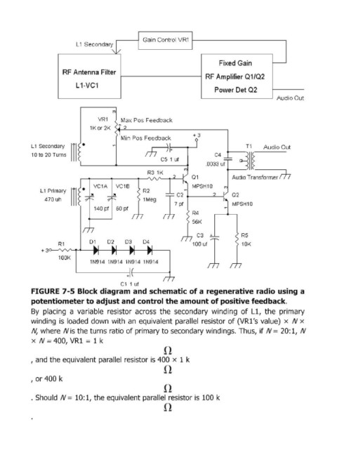
FI GURE 7-5 Block diagram and schematic of a regenerative radio using a
potentiometer to adjust and control the amount of positive feedback.
By placing a variable resistor across the secondary winding of L1, the primary
winding is loaded down with an equivalent parallel resistor of (VR1's value) x N x
N, where N is the turns ratio of primary to secondary windings .. Thus, if N = 20: 1, N
x N ~ 400, VR1 = 1 k
, and the equivalent parallel resistor is 400 x 1 k
, or 400 k
. Should N = 10: 1, the equivalent parallel resistor is 100 k