
Page 106 - Build Your Own Transistor Radios a Hobbyists Guide to High-Performance and Low-Powered Radio Circuits
P. 106
RF Gain
~-----------------7 Gain Control
Threshold of Oscillation /['..
/ / /
L-L-_______ -1-______ .l.-_~) Gain Control
10 Turns Secondary 4 Turns Secondary 1 Turn Secondary
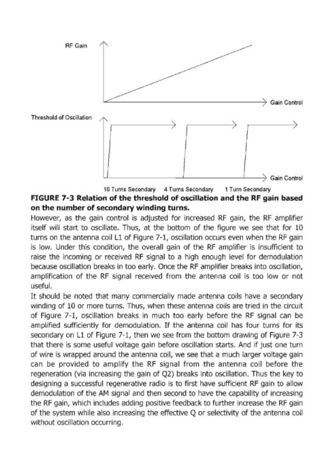
FIGURE 7-3 Relation of the threshold of oscillation and the RF gain based
on the number of secondary winding turns.
However, as the gain control is adjusted for increased RF gain, the RF amplifier
itself will start to oscillate. Thus, at the bottom of the figure we see that for 10
turns on the antenna coil Ll of Figure 7-1, oscillation occurs even when the RF gain
is low. Under this condition, the overall gain of the RF amplifier is insufficient to
raise the incoming or received RF signal to a high enough level for demodulation
because oscillation breaks in too early. Once the RF amplifier breaks into oscillation,
amplification of the RF signal received from the antenna coil is too low or not
useful.
It should be noted that many commercially made antenna coils have a secondary
winding of 10 or more turns. Thus, when these antenna coils are tried in the circuit
of Figure 7-1, oscillation breaks in much too early before the RF signal can be
amplified sufficiently for demodulation. If the antenna coil has four turns for its
secondary on L1 of Figure 7-1, then we see from the bottom drawing of Figure 7-3
that there is some useful voltage gain before oscillation starts. And if just one turn
of wire is wrapped around the antenna coil, we see that a much larger voltage gain
can be provided to amplify the RF signal from the antenna coil before the
regeneration (via increasing the gain of Q2) breaks into oscillation. Thus the key to
designing a successful regenerative radio is to first have sufficient RFgain to allow
demodulation of the AM signal and then second to have the capability of increasing
the RF gain, which includes adding positive feedback to further increase the RF gain
of the system while also increasing the effective Q or selectivity of the antenna coil
without oscillation occurring.