
Page 105 - Build Your Own Transistor Radios a Hobbyists Guide to High-Performance and Low-Powered Radio Circuits
P. 105
positive-feedback regenerative system to achieve a balance between having Q2
provide further amplification of the RF signal (without oscillation) and also providing
Q multiplication to increase the Q or selectivity of Ll. For example, if the number of
turns is too many, the positive-feedback regenerative system will break into
oscillation before the received signal can be demodulated in a satisfactory manner.
L 1 Secondary
"- /
RF Amplifier 01/02
RF Antenna Filter
L 1-VC1
( . L 1 Secondary
+3 i 10 Turns + 3
<j>
'"
2 ...r Ql
r. MPSH10
-
'"
i • L 1 Primary ~ Ve l RF ? .Y Q2
100 Turns ;;
'"
MPSH10
Rl -
+ 1 .6 reI
20K
r/7 R2
2K
117
Oscillator Circuit r, '7
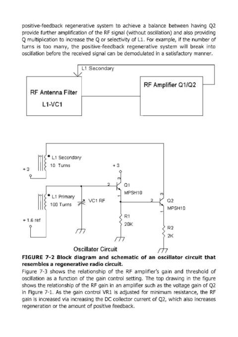
FIGURE 7-2 Block diagram and schematic of an oscillator circuit that
resembles a regenerative radio circuit.
Figure 7-3 shows the relationship of the RF amplifier's ga in and threshold of
oscillation as a function of the gain control setting. The top drawing in the figure
shows the relationship of the RF gain in an amplifier such as the voltage gain of Q2
in Figure 7-l. As the gain control VRl is adjusted for minimum resistance, the RF
gain is increased via increasing the DC collector current of Q2, which also increases
regeneration or the amount of positive feedback.