Page 102 - Build Your Own Transistor Radios a Hobbyists Guide to High-Performance and Low-Powered Radio Circuits
P. 102

RF amplifier.  Also the leads of the secondary may have to be reversed.  Refer to the

            note at the end of this chapter.
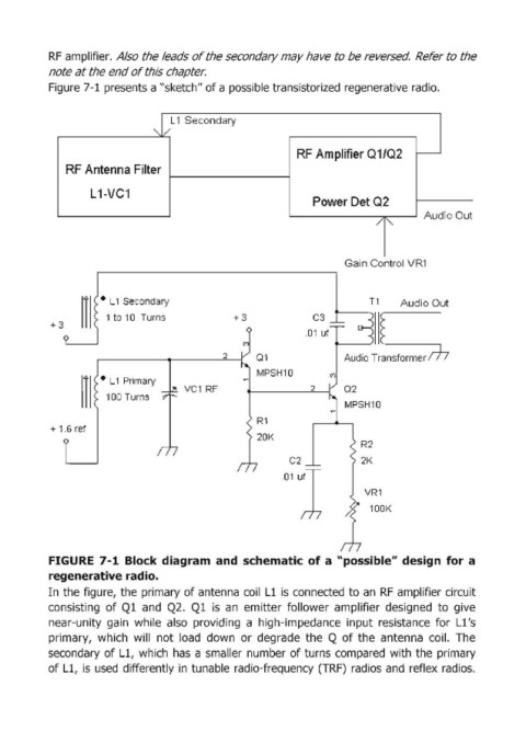
            Figure 7-1  presents a "sketch" of a possible transistorized regenerative radio.


                                         1
                                    ~ Secondary
                                        L
              r----------->l......,
                                                                    RF Amlplifier Q1/Q2         r---
                RF Antenna Filter


                     L 1-VC1
                                                                        Power Det Q2
                                                                                                 Audio Out


                                                                               Gai n Control VR1


                        •  L 1 Secondary                                             T1     Audio Out
                                                                                       C
                           to  10  Turns              +3                C3
                                                                      .01  uf

                       ~ ___ ~~ __ ~2~  01                                     Audio Transformer JI""f?
                                                           MPSH10
                        •  L 1 Primary
                                           VC1  RF       4t-------=2'----i  02
                         100 Turns
                                                                               MPSH10

            + 1.6 ref

                                                                                   R2
                                                                 , l                VR1
                                                                                   2K
                                                                   C2
                                                                  Olu


                                                                                     100K


            FIGURE  7-1  Block diagram: and  schematic of a  "possible" design  for a
            regenerative radio.

            In the figure,  the primary of antenna  coil  Ll is  connected  to an  RF  amplifier circuit
            consisting  of Ql  and  Q2.  Ql  is  an  emitter  follower  amplifier  designed  to  give
            near-unity  gain  while  also  providing  a  high-impedance  input  resistance  for  Ll's
            primary,  which  will  not  load  down  or  degrade  the  Q of the  antenna  coil.  The
            secondary  of Ll, which  has  a smaller  number of turns compared  with  the  primary
            of Ll, is  used  differently in  tunable  radio-frequency (TRF)  radios and  reflex  radios.
   97   98   99   100   101   102   103   104   105   106   107