
Page 99 - Build Your Own Transistor Radios a Hobbyists Guide to High-Performance and Low-Powered Radio Circuits
P. 99
· If the DC current is raised to 10 mA by changing R8 to about 30
, then T2's primary impedance is about 3/0.010 = 300
· Because of the "highll current drain, a power switch in series with the battery will
prolong battery life. See the following table.
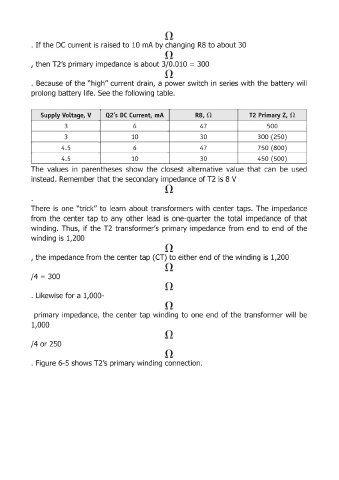
SuppLy VoLtage, V 02'5 DC Current, mA R8, n T2 Primary Z, n
3 6 47 500
3 10 30 300 (250)
4.5 6 47 750 (800)
4.5 10 30 450 (500)
The values in parentheses show the closest alternative value that can be used
instead. Remember that the secondary impedance of T2 is 8 V
There is one "trick" to learn about transformers with center taps. The impedance
from the center tap to any other lead is one-quarter the total impedance of that
winding. Thus, if the T2 transformer's primary impedance from end to end of the
winding is 1,200
, the impedance from the center tap (CT) to either end of the winding is 1,200
/4 = 300
· Likewise for a 1,000-
primary impedance, the center tap winding to one end of the transformer will be
1,000
/4 or 250
· Figure 6-5 shows T2's primary winding connection.