
Page 97 - Build Your Own Transistor Radios a Hobbyists Guide to High-Performance and Low-Powered Radio Circuits
P. 97
1. Ql was tried originally with a high current gain (beta or Hfe) transistor, a
2N5089. This transistor performed poorly with very bad selectivity in this reflex
radio circuit.
2. Ql then was changed to a general-purpose transistor, the 2N4124, which gave
satisfactory results but with a little less gain than the low-capacitance MPSH 10
transistor.
Multiple-Transistor Reflex Radio Circuit
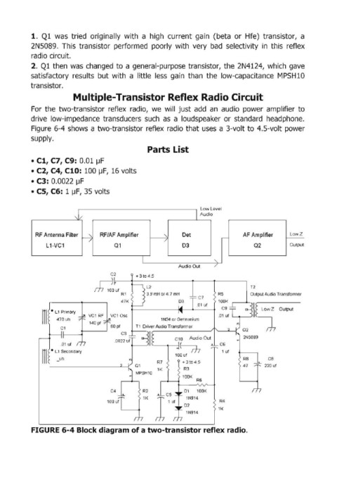
For the two-transistor reflex radio, we will just add an audio power amplifier to
drive low-impedance transducers such as a loudspeaker or standard head phone.
Figure 6-4 shows a two-transistor reflex radio that uses a 3-volt to 4.5-volt power
supply.
Parts List
• C1, C7, C9: 0.01 lJF
• C2, C4, Cl0: 100 lJF, 16 volts
• C3: 0.0022 lJF
• CS, C6: 1 lJF, 35 volts
L
L oweve I
,J/ I Audio
RF Antenna Filter RF/AF Amplifier "\ Det AF Amplifier LowZ
-j / ,---
L 1-VC1 01 D3 02 Output
I "-
AudIO Out /
C2
~Uf L2 T2
R1 3.9 mH or4.7 mH R5 Output Audio Transformer
C7
03
.01 ut
III • L1 Pnma~ VC1 Osc
1 N34 or Germanium
140 pt
60 pt T1 Driver Audio Transformer
C3
C10 Audio Out
.0022 ut
t----m
100 ut
CB
R7 + 3 to 4.5
220 uf
1K R3
R4
1K
1N914
FIGURE 6-4 Block diagram of a two-transistor reflex radio.