
Page 107 - Build Your Own Transistor Radios a Hobbyists Guide to High-Performance and Low-Powered Radio Circuits
P. 107
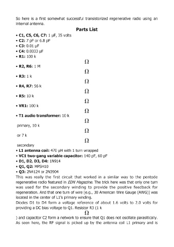
So  here  is  a  first  somewhat  successful  transistorized  regenerative  radio  using  an

            internal antenna.
                                                     Parts List
            • Cl, CS, C6, C7:  1 J..IF,  35 volts

            •  C2: 7 pF or 6.8 pF
            •  C3: 0.01  J..IF
            •  C4: 0.0033 J..IF

            •  Ri: 100 k


            •  R2, R6:  1 M


            •  R3:  1 k


            •  R4, R7: 56 k


            •  RS:  10 k


            • VR1:  100 k


            • Tl audio transformer: 10 k


             primary,  10 k


             or 7 k


             secondary
            •  Ll antenna coil:  470 J..IH  with 1 turn wrapped
            • VCl two-gang variable capacitor:  140 pF, 60 pF
            •  01, 02, 03, 04: 1N914
            • Ql, Q2:  MPSH 10

            • Q3:  2N4124 or 2N3904
            This  was  really  the  first  circuit  that  worked  in  a  similar  way  to  the  pentode
            regenerative radio featured  in  EDN Magazine.  The trick here was that only one turn
            was  used  for  the  secondary  winding  to  provide  the  positive  feedback  for

            regeneration.  And  that one turn of wire [e.g., 30 American Wire Gauge (AWG)] was
            located in the center of Ll's primary winding.
            Diodes  D1  to  D4  form  a  voltage  reference  of about  1.6  volts  to  2.0  volts  for
            providing a DC bias voltage to Q1.  Resistor R3  (1  k


            ) and capacitor C2 form a network to ensure that Ql does not oscillate parasitically.
            As  seen  here,  the  RF  signal  is  picked  up  by  the  antenna  coil  Ll  primary  and  is