
Page 109 - Build Your Own Transistor Radios a Hobbyists Guide to High-Performance and Low-Powered Radio Circuits
P. 109
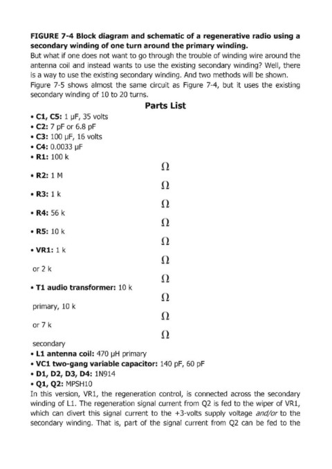
FIGURE 7-4 Block diagram and schematic of a  regenerative radio using a
            secondary winding of one turn around the primary winding.
            But what if one does not want to go through the trouble of winding wire around the
            antenna  coil  and  instead  wants to use  the  existing  secondary winding?  Well,  there
            is a way to use the existing secondary winding. And two methods will be shown.
            Figure  7-5  shows  almost  the  same  circuit  as  Figure  7-4,  but  it uses  the  existing

            secondary winding of 10 to 20 turns.
                                                     Parts List

            • Cl, cs:  1 ~F, 35 volts
            • C2: 7 pF or 6.8 pF
            • C3:  100 pF,  16 volts
            • C4: 0.0033 IJF

            •  Rl: 100 k


            •  R2:  1 M


            •  R3:  1 k


            •  R4:  56 k


            •  RS:  10 k


            • VR1:  1 k


             or 2 k


            • Tl audio transformer: 10 k


             primary,  10 k


             or 7 k


             secondary
            •  Ll antenna coil:  470 IJH  primary
            • Vel two-gang variable capacitor:  140 pF,  60 pF

            •  01, 02, 03, 04: lN914
            • Ql, Q2:  MPSH 10
            In  this  version,  VR1,  the  regeneration  control,  is  connected  across  the  secondary
            winding  of L1.  The  regeneration  signal  current from  Q2  is  fed  to the wiper of VR1,
            which  can  divert this  signal  current  to the  +3-volts  supply  voltage  and/or to  the

            secondary  winding.  That  is,  part  of the  signal  current from  Q2  can  be  fed  to the