
Page 108 - Build Your Own Transistor Radios a Hobbyists Guide to High-Performance and Low-Powered Radio Circuits
P. 108
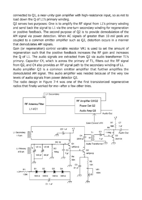
connected to Q1, a near-unity gain amplifier with high-resistance input, so as not to

            load down the Q of Ll's primary winding.
            Q2  serves two purposes:  One  is to amplify the RF  signal  from  Ll's primary winding
            and  send  back the signal to Ll via  the one-turn secondary winding  for regeneration
            or  positive  feedback.  The  second  purpose  of Q2  is  to  provide  demodulation  of the
            AM  signal  via  power  detection.  When  AC  signals  of greater than  10  mV  peak  are
            coupled  to  a common  emitter  amplifier  such  as  Q2,  distortion  occurs  in  a manner

            that demodulates AM  signals.
            Gain  (or  regeneration)  control  variable  resistor  VR1  is  used  to  set  the  amount  of
            regeneration  such  that the  positive  feedback  increases  the  RF  gain  and  increases
            the  Q of Ll.  The  audio  signals  are  extracted  from  Q2  via  audio  transformer Tl's
            primary.  Capacitor C4,  which  is  across  the  primary of Tl, filters  out the  RF  signal

            from Q2, and C4 also provides an  RF signal  path to the secondary winding of Ll.
            Audio  amplifier  Q3  is  a  common  emitter  amplifier  that  further  amplifies  the
            demodulated  AM  signal.  This  audio  amplifier was  needed  because  of the  very  low
            levels of audio signals from  power detector Q2.
            The  radio  design  in  Figure  7-4  was  one  of the  first  transistorized  regenerative

            radios that finally worked for me-after a few other tries.


                                    ,I... L 1 Secondary

                                                                 RF Amplifier 01/02  -
                      RF Antenna Filter
                                                                    Power Det Q2
                          L 1·VC1
                                                                    Audio Amp 03
                                                                                       Audio Out
                                                                               /   I'
                                                                                                 +3

                                                                         Gain Control V RI    R7     C7
                                                                                              56K    '"'
                                                    CS  1 ut   +3                          R6
                                                              j
            L 1 Secondary                      m-l~                    1-n          Cl               Audio Out
                        mi-                                       003~4~  lie "                   2N4124
               1 Turn                                                                             a3

                                                R31K                     Audio Transformer m
                                                             al
                            •   VC 1A   VC 1S                MPSH10
               L 1 Primary                    R2                         a2
                        m                                                 MPSH1Q
                470 uh                        lMeg
                               140 pt  60 pt        lC;
                                                             R4
                                                             56K
                                                                            R5
                                                                C3          lOK
                              Dl     D2      D3     04
                    Rl                                                            VRl
               +3                                              "1                 lOOK
                    l OOK
                              lN914   lN914   lN914   lN914

                                       Cllut