
Page 143 - Build Your Own Transistor Radios a Hobbyists Guide to High-Performance and Low-Powered Radio Circuits
P. 143
It should be noted that the reader also can replace the ferrite antenna coil L1in
Figure 9-4 with a loop antenna and an RF transformer (actually an oscillator coil
used as an RF coil), such as the 42IF100, 42IF110, or 42IF300 coil. The loop
antenna will be connected to the low-side tap of the RF transformer at the primary
winding, the variable capacitor VC1's RF section will be connected to the primary
winding, and the other end of the primary winding will be grounded. The secondary
winding of the RF transformer will be connected in the same way as the secondary
winding of L1 in Figure 9-4. For a reference, see Figure 8-8 for the schematic
pertaining to the loop antenna and T7.
Photos of Low-Power AM Superheterodyne Radios
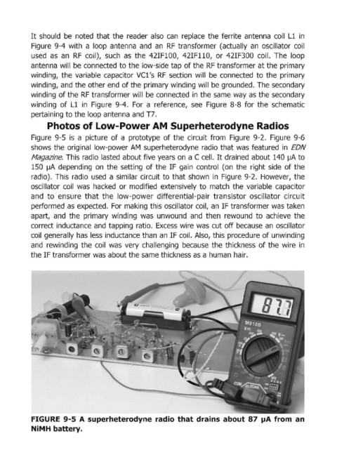
Figure 9-5 is a picture of a prototype of the circuit from Figure 9-2. Figure 9-6
shows the original low-power AM superheterodyne radio that was featured in EDN
Magazine. This radio lasted about five years on a C cell. It drained about 140 ~A to
150 IJA depending on the setting of the IF gain control (on the right side of the
radio). This radio used a similar circuit to that shown in Figure 9-2. However, the
oscillator coil was hacked or modified extensively to match the variable capacitor
and to ensure that the low-power differential-pair transistor oscillator circuit
performed as expected. For making this oscillator coil, an IF transformer was taken
apart, and the primary winding was unwound and then rewound to achieve the
correct inductance and tapping ratio. Excess wire was cut off because an oscillator
coil generally has less inductance than an IF coil. Also, this procedure of unwinding
and rewinding the coil was very challenging because the thickness of the wire in
the IF transformer was about the same thickness as a human hair.
FIGURE 9-5 A superheterodyne radio that drains about 87 pA from an
NiMH battery.