
Page 146 - Build Your Own Transistor Radios a Hobbyists Guide to High-Performance and Low-Powered Radio Circuits
P. 146
circuit, which can lead to parasitic oscillations. In addition, the higher collector
current leads to higher oscillation signals at the collector of the converter transistor,
which robs the audio-signal's voltage swing. Therefore, it is desirable to limit the
oscillator's output voltage.
Another design consideration for a one-transistor superheterodyne receiver is
demodulation after the IF filter. Because the converter oscillator transistor is
running at such a high collector current, there is a tremendously large oscillator
signall at input of the IF filter that does not get filtered out. This large oscillator
signal added on top of the IF signal then hampers envelope detection of the
455-kHz IF signal. In reality, for single-tuned IF transformers, the signal from the
output of the first IF transformer contains both signals from the IF of 455 kHz and
also the oscillator frequency, which ranges from 1 MHz to 2 MHz. Usually, the first
IF amplifier does not have a problem handling both signals, and the output from
the first IF amplifier is fed to a second IF transformer, which then filters out almost
completely the oscillator signal while passing the 455-kHz IF signal.
Thus at least two stages of IF filtering may be required to reject the oscillator's
signal from the converter oscilllator circuit while allowing the 455-kHz IF signal to be
envelope detected.
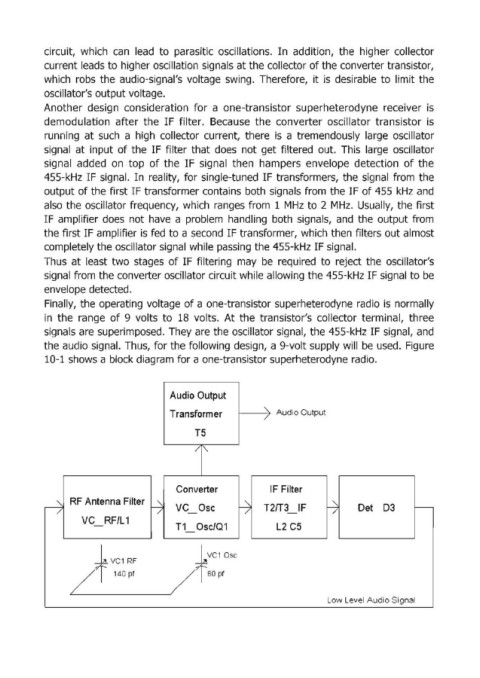
Finally, the operating voltage of a one-transistor superheterodyne radio is normally
in the range of 9 volts to 18 volts. At the transistor's collector terminal, three
signals are superimposed. They are the oscillator signal, the 455-kHz IF signal, and
the audio signal. Thus, for the following design, a 9-volt supply will be used. Figure
10-1 shows a block diagram for a one-transistor superheterodyne radio.
Audio Output
Transform er > Audio Output
T5
/ ["
Converter IF Filter
r RF Antenna Filter ~ VC Ose --j T2fT3 IF ~ Det D3 r---
/
/
-
-
VC RF/L 1
- T1 Ose/Q1 L2 CS
+VC10SC
VCl
+ Rf
/ 140 pt / GO pt
Low Level Audio Signal