
Page 149 - Build Your Own Transistor Radios a Hobbyists Guide to High-Performance and Low-Powered Radio Circuits
P. 149
C1100ur
+---, ,----- Audio Output
03
lN270
R3 C6
47K ,*0.0039 uf
I1I • L1 Seconda~
C9
R1
04
180
l N270
+9
R4
20K
421F110 Pin Out
ToT2 6 3
01
cs
2 ToC4 1 uf lN914
1 -- 02
ToQ1 4 VC1 Osc lN914
Bottom View
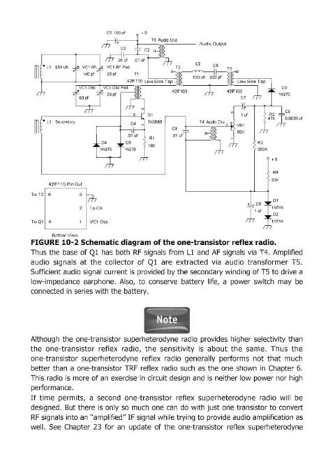
FIGURE 10-2 Schematic diagram of the one-transistor reflex radio.
Thus the base of Ql has both RF signals from Ll and AF signals via T4. Amplified
audio signals at the collector of Ql are extracted via audio transformer TS.
Sufficient audio signal current is provided by the secondary winding of TS to drive a
low-impedance earphone. Also, to conserve battery life, a power switch may be
connected in series with the battery.
Although the one-transistor superheterodyne radio provides higher selectivity than
the one-transistor reflex radio, the sensitivity is about the same. Thus the
one-transistor superheterodyne reflex radio generally performs not that much
better than a one-transistor TRF reflex radio such as the one shown in Chapter 6.
This radio is more of an exercise in circuit design and is neither low power nor high
performance.
If time permits, a second one-transistor reflex superheterodyne radio will be
designed. But there is only so much one can do with just one transistor to convert
RF signals into an "amplified" IF signal while trying to provide audio amplification as
well. See Chapter 23 for an update of the one-transistor reflex superheterodyne