
Page 151 - Build Your Own Transistor Radios a Hobbyists Guide to High-Performance and Low-Powered Radio Circuits
P. 151
T4Audio Audio Driver Signal T5 Audio
A
> udio Output
Driver Output
/' /'
" "
, 1/
Converter/AF IF Amplifier
Antenna J
~ ~ IF Filter 1 ~ ~ IF Filter 2 ~ I-
7 7 VC_ Osc 7 7 Audio Output 7 7 Det D3
L1 VC RF T2 IF T3 IF
T1_ 05c/01 02
+VCl D~
-::? VC1 RF
/ ...... 140pr 60 pr
Low Level Audio Signal
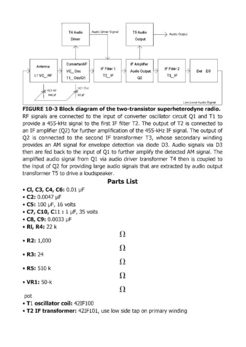
FIGURE 10-3 Block diagram of the two-transistor superheterodyne radio.
RF signals are connected to the input of converter oscillator circuit Ql and Tl to
provide a 455-kHz signall to the first IF filter T2. The output of T2 is connected to
an IF amplifier (Q2) for further amplification of the 455-kHz IF signal. The output of
Q2 is connected to the second IF transformer T3, whose secondary winding
provides an AM signal for envelope detection via diode D3. Audio signals via D3
then are fed back to the input of Ql to further amplify the detected AM signal. The
amplified audio signal from Ql via audio driver transformer T4 then is coupled to
the input of Q2 for providing large audio signals that are extracted by audio output
transformer T5 to drive a loudspeaker.
Parts List
• Cl, C3,C4, C6: 0.01 ~F
• C2: 0.0047 IJF
• cs: 100 JJF, 16 volts
• C7, Cl0, C11 : 1 IJF, 35 volts
• C8,C9: 0.0033 IJF
• RI, R4: 22 k
• R2: 1,000
• R3: 24
• RS: 510 k
• VR1: 50-k
pot
• T1 oscillator coil: 42IF100
• T2 IF t ransformer: 42IF101, use low side tap on primary winding