
Page 156 - Build Your Own Transistor Radios a Hobbyists Guide to High-Performance and Low-Powered Radio Circuits
P. 156
One characteristic of a ceramic filter is that unlike an inductor, the direct-current
(DC) resistance is very high, just like an open circuit. Another feature of a ceramic
filter is that it is meant to be driven and terminated by a specified resistance. Most
AM band ceramic filters, for example, have driving and terminating resistances from
1,000 V to about 3,000 V. And ceramic filters may be specified for a wide
bandwidth such as 10 kHz to a narrow bandwidth of 3 kHz.
Although ceramic filters have a response like a typical LC band-pass filter near the
pass-band frequencies, they do suffer from allowing out-of-band signals to pass
through. And, in general, the specified frequency response of a ceramic filter
includes an IF transformer preceding it to help remove spurious or out-of-band
signals such as the local oscillator signal that is from 1 MHz to 2 MHz.
Manufacturers of ceramic filters include Murata, Toko, and Token. Note that AM
(and FM) band ceramic filters can be obtained from www.mouser.com.
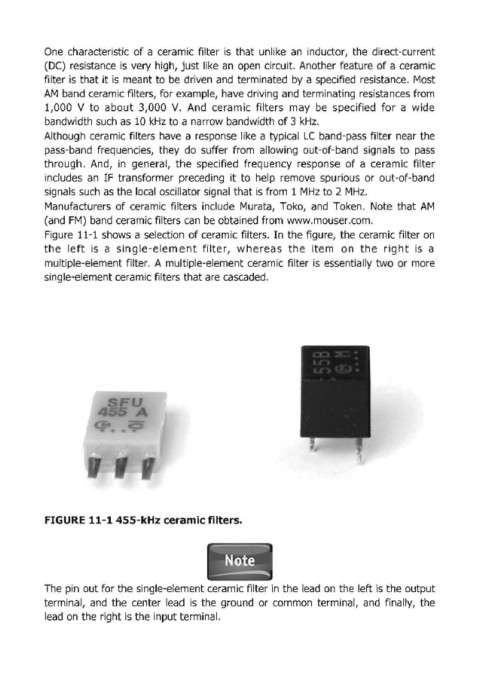
Figure 11-1 shows a selection of ceramic filters. In the figure, the ceramic filter on
the left is a single-element filter, whereas the item on the right is a
multiple-element filter. A multiple-element ceramic filter is essentially two or more
single-element ceramic filters that are cascaded.
FIGURE 11-1 455-kHz ceramic filters.
~
-
Note
The pin out for the single-element ceramic filter in the lead on the left is the output
terminal, and the center lead is the ground or common terminal, and finally, the
lead on the right is the input terminal.