
Page 158 - Build Your Own Transistor Radios a Hobbyists Guide to High-Performance and Low-Powered Radio Circuits
P. 158
provides a local oscillator signal from about 1 MHz to 2 MHz via coupling the
oscillation signal from the secondary to primary windings. A multiplying effect
between the RF signal and the local oscillator signal occurs via a large oscillator
signal at the emitter of Ql and a small RF signal at the base of Q1. Thus at the
collector of Ql there is an IF signal as well as a very large-amplitude oscillator
signal. Because the ceramic filters have poor rejection for some out-of-band
signails, including the oscillator signal, two 455-kHz ceramic filters (CFl and CF2)
are used to extract the 455-kHz IF signal. From the output of ceramic filter CF2 is a
usable IF signal for further amplification via the first IF amplifier transistor Q2. The
collector terminal output of Q2 is then fed to a single ceramic filter CF3 whose filter
output is connected to the input of the second IF amplifier Q3. The output collector
terminal at Q3 now provides an IF signal for envelope detection via diode D3. Thus
audio signals are provided at C8 for a crystal earphone or the audio signals may be
connected to an audio amplifier. Note that D3 is rectifying the negative portion of
the AM envelope because the positive portion actually goes into clipping when a
strong signal is received. However, the negative portion of the AM envelope at the
collector of Q3 is not affected and does not clip. Also, to conserve energy, a power
switch may be connected in series with the battery or power source.
+3
C2 1 ut R9
m-1 47K
R2 R7
3000
T1
C7
n IO'w
esT
TT
C3
+3
.01 uf R6
R3
Rl 22K
22K
42 1F1 00 Pin Out
01
Cl C4
'
l oO l'w lN914 To R2 6 3
uf
02
lN914 2 ToC3
To 01 4 1 VC10sc
Bottom View
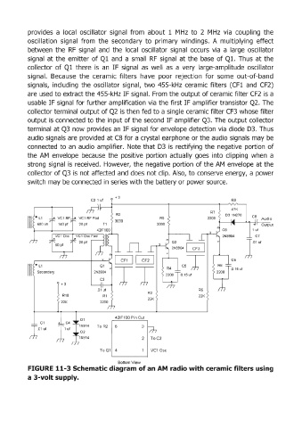
FIGURE 11-3 Schematic diagram of an AM radio with ceramic filters using
a 3-volt supply.