
Page 163 - Build Your Own Transistor Radios a Hobbyists Guide to High-Performance and Low-Powered Radio Circuits
P. 163
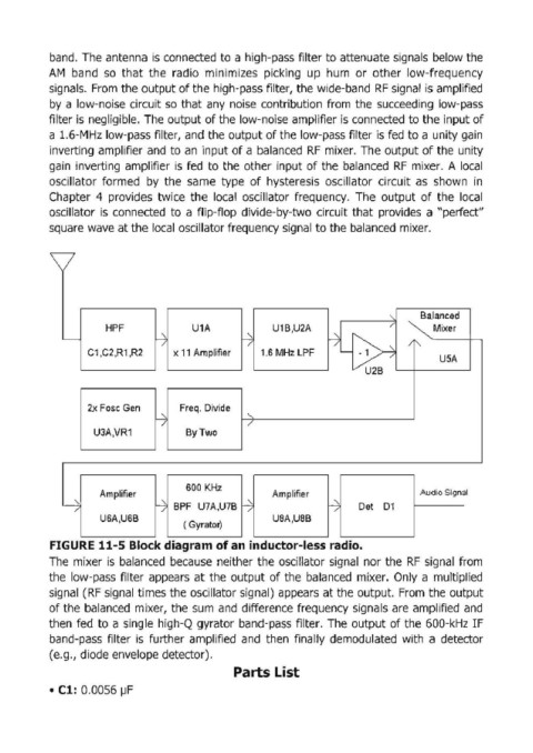
band.  The antenna  is connected  to a high-pass filter to attenuate signals  below the

            AM  band  so  that  the  radio  minimizes  picking  up  hum  or  other  low-frequency
            signals.  From the output of the high-pass filter, the wide-band  RF  signal  is amplified
            by  a low-noise circuit so  that  any  noise  contribution from  the  succeeding  low-pass
            filter is  negligible. The output of the low-noise amplifier is connected to the input of
            a 1.6-MHz low-pass filter,  and the output of the low-pass filter is fed  to a unity gain
            inverting amplifier and  to an  input of a balanced  RF  mixer.  The output of the  unity
            gain  inverting  amplifier  is  fed  to  the other input of the  balanced  RF  mixer.  A local

            oscillator  formed  by  the  same  type  of hysteresis  oscillator  circuit  as  shown  in
            Chapter  4  provides  twice  the  local  oscillator  frequency.  The  output  of  the  local
            oscillator  is  connected  to  a flip-flop  divide-by-two  circuit  that  provides  a "perfect"
            square wave at the local oscillator frequency signal to the balanced  mixer.


                                                                                                  Mixer
                         HPF                U1A               U1B,U2A       ,           "      Balanced
                                                                                        /
                                    -7                  /                 rj L-~
               ~                                       r..::
                                                                                            /
                     C1 ,C2,R1 ,R2      x 11 Amplifier     1.S MHz LPF                        "
                                                                                                   U5A
                                                                                   U2B

                     2x Fasc Gen         Freq. Divide
                                    -7                  "
                                                        /
                      U3A,VR1              By Two


                                           SOO  KHz
                       Amplifier                              Amplifier                        Audio Signal
               y                    ...:;   BPF  U7A,u7B r..::            H      Det  01
                  /                  /                  /                   /
                       USA,USB                                USA,USB
                                          ( Gyrator)
                                       .                 .                     .
            FIGURE 11-5 Block diagram of an  tnductor-Iess radio.
            The  mixer  is  balanced  because  neither the oscillator signal  nor the  RF  signal  from
            the  low-pass  filter  appears  at the  output of the  balanced  mixer.  Only  a multiplied
            signal  (RF  signal  times the oscillator signal)  appears at the output.  From the output
            of the  balanced  mixer, the sum  and  difference frequency  signals are  amplified and
            then  fed  to  a single  high-Q  gyrator band-pass filter.  The  output of the  600-kHz IF

            band-pass  filter  is  further  amplified  and  then  finally  demodulated  with  a  detector
            (e.g., diode envelope detector).
                                                     Parts List

            • Cl: 0.0056 IJF