Page 167 - Build Your Own Transistor Radios a Hobbyists Guide to High-Performance and Low-Powered Radio Circuits
P. 167

0"            CI6   I OK

                 WK         T  10Dut
                           rh     + 5  CI3
                   0"
                    U'K    0"       o.o~
                           JOK
                                                C24  om ut ~       U""                  U6B
            To U2B                                                         "'"         NE5532
            ~~~,~1=~t~~~:0,~a~2K~ __ ~                                     WK
                                     74HC40531
             Pin 7   0.01  ut         U5A
                                                C23
            ToU2A                       U5B     47 pt             0"                   023
                                     74HC4053      RI9
             Pin  1
                     0.01  ut                      47K            3900                 3900
                                                            020          C27       R22
                                               +4.5                   0.15 ur J
                                                            lKl%                   lK 1%
            To U4APin6
                                                      C25;J;  O.D1u!         C28;r,  om ut
                                                                         .,
                                   + 4.5
                            I
                    rh,-----1 F-----l                                                              C35
                                        .,                               UBA          uaB           (  Audio
              R24       C31  1 00 ut   R27
              lOOK                  511                                             NE5532            0",
                        C30   510 pf     C37  ~
                ,------1                                                                           ""
                                         UIA'  rh
                 R25   511               LME491:20                                           lN210
                   U7B                             0"                  029          0"
                                                                                                          0"
                                                   '"             0"   :;1900    0"   3900                lOOK
                                  pr
              ______ --j C29  h rh                                lK  I'll.      lKl%
                LME49720
            L                         R26  511              en 117  O.Olut   C33 iJ7  0,01  ut

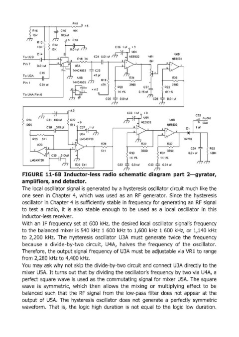
            FIGURE  11-68 Inductor-Iess  radio  schematic diagram  part  2-gyrator,
            amplifiers, and detector.
            The  local oscillator signal  is generated by a hysteresis oscillator circuit much like the
            one  seen  in  Chapter  4,  which  was  used  as  an  RF  generator.  Since  the  hysteresis
            oscillator in  Chapter 4 is  sufficiently stable in  frequency for generating an  RF  signal

            to  test  a  radiO,  it  is  also  stable  enough  to  be  used  as  a  local  oscillator  in  this
            inductor-Iess receiver.
            With  an  IF  frequency set at 600  kHz,  the desired  local  oscillator signal's  frequency
            to the balanced  mixer is  S40  kHz  1 600  kHz  to  1,600 kHz  1 600  kHz,  or  1,140 kHz

            to  2,200  kHz.  The  hysteresis  oscillator  U3A  must  generate  twice  the  frequency
            because  a  divide-by-two  circuit,  U4A,  halves  the  frequency  of  the  oscillator.
            Therefore,  the output signal  frequency of U3A must be  adjustable via  VRl to range
            from  2,280 kHz to 4,400 kHz.
            You  may ask why not skip the divide-by-two circuit and connect U3A directly to the
            mixer USA. It turns out that by dividing the oscillator's frequency by two via  U4A,  a

            perfect square  wave  is  used  as  the commutating  signal  for mixer USA.  The square
            wave  is  symmetric,  which  then  allows  the  mixing  or  multiplying  effect  to  be
            balanced  such  that the  RF  signal  from  the  low-pass  filter  does  not  appear  at the
            output  of  USA.  The  hysteresis  oscillator  does  not  generate  a  perfectly  symmetric
            waveform.  That  is,  the  logic  high  duration  is  not equal  to  the  logic  low  duration.
   162   163   164   165   166   167   168   169   170   171   172