
Page 170 - Build Your Own Transistor Radios a Hobbyists Guide to High-Performance and Low-Powered Radio Circuits
P. 170
does not have too much RF filtering in the front end, it is susceptible to overload
when used near a transm,itter (e.g., amateur radio FM repeater). But otherwise it
performs very well.
Another popular implementation of the SDR is via several dO-it-yourself
software-defined radio programs that run on a computer, such as the Winrad
program. There are other SDR programs that will run on PCs. For example, once
the Winrad program is installed on a PC (e.g., XP or Windows 7 operating system),
all that is needed is a down-converted low-frequency IF signal to be provided to the
audio inputs of the computer's sound card. The PC then takes over the IF filtering,
tuning, and demodulation. Because the low-frequency IF signal has a wide
bandwidth of at least half the sampling frequency of the sound card, radio stations
can be tuned via the Winrad software program over a 201-kHz range. Thus the
Winrad program also provides the equivalent of a variable-frequency oscillator.
For many SDRs, switch-mode mixers will be used, and image rejection will be
handled in the software via digital signal processing. So now let's look at two
examples of SDR front-end systems. They both provide two channels of
down-converted low-frequency IF signals to the two input channels of a computer's
sound card.
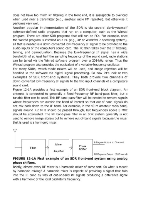
Figure 12-1A provides a first example of an SDR front-end block diagram. An
antenna is connected to generally a fixed-frequency RF band-pass filter, but a
tunable filter can be used. This RF band-pass filter will be needed to remove signals
whose frequencies are outside the band of interest so that out-of-band signals do
not mix back down to the IF band. For example, in the 40-m amateur radio band,
signals around 7.2 MHz should be passed through, but frequencies above 8 MHz
should be attenuated. The RF band-pass filter in an SDR system generalily is not
used to remove image signals but to remove out-of-band signals because the mixer
that is used is a harmonic mixer.
o Degree Output (I Channel)
Mixer
- Filter ~ ~ Phase
Shifter
/
/
Amplifier
90 Degree s Output ( Q Channel)
FIGURE 12-1A First example of an SDR front-end system using analog
phase shifters.
Briefly, almost every RF mixer is a harmonic mixer of some sort. So what is meant
by harmonic mixing? A harmonic mixer is capable of providing a signal that falls
into the IF band by way of out-of-band RF signals producing a difference signal
with a harmonic of the local oscillator's frequency.