
Page 173 - Build Your Own Transistor Radios a Hobbyists Guide to High-Performance and Low-Powered Radio Circuits
P. 173
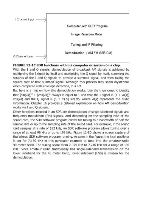
I Channel  Input  --)~


                                                         Corn puter with SDR Program


                                                            Ilmage Rejection Mixer


                                                            Tuning and IF Filtering


                                                       Demodulation  ( AM FM SSB CW)
            Q Channel Input
                                      /

            FIGURE 12-1C SDR functions within a computer or system on a chip.

            With  the  I  and  Q signals,  demodulation  of broadcast  AM  signals  is  achieved  by
            multiplying the I  signal  by itself and  multiplying the Q signal  by itself, summing the
            squares  of the  I  and  Q signals  to  provide  a  summed  signal,  and  then  taking  the
            square  root  of that  summed  signal.  Although  this  process  may  seem  mysterious
            when compared with envelope detection,  it is not.

            But  here  is  a  hint on  how this demodulation  works:  Use  the trigonometric  identity
            that [sin(Btjf +  [cos(Bt)f always  is  equal  to  1 and  that the I  signal  is  [1  +  Ili(t)]
            cos(Bt)  and  the  Q signal  is  [1  1  m(t)]  sinCBt),  where  rrt...t)  represents  the  audio
            information.  Chapter  16  provides  a  detailed  explanation  on  how AM  demodulation

            works via I  and Q signals.
            Other functions included  in an  SDR are demodulation of single-sideband signals and
            frequency-modulation  (FM)  signals.  And  depending  on  the  sampling  rate  of the
            sound  card,  the SDR software program allows for tuning to a bandwidth of half the
            sample rate or up to the sampling  rate of the sound card.  For example, if the sound
            card  samples  at a  rate  of 192  kHz,  an  SDR  software  program  allows tuning  over a

            range of at least 96  kHz  or up to 192 kHz.  Figure  12-1D shows a screen capture of
            the Winrad SDR software program running. As seen  in the figure, the local  oscillator
            is  set  for  7,150  kHz  in  this  particular  example  to  tune  into  the  amateur-radio
            40-meter band.  The tuning  spans  from  7,054  kHz  to 7,246  kHz  for a range of 192
            kHz.  Since  amateur  radio  traditionally  has  single-sideband  transmission  on  the

            lower  sideband  for  the  40-meter  band,  lower  sideband  (LSB)  is  chosen  for  the
            demodulation.