
Page 177 - Build Your Own Transistor Radios a Hobbyists Guide to High-Performance and Low-Powered Radio Circuits
P. 177
ANTENNA
'-,/
T1
RF Transf.
~ ± Amplifier or Mixer
o
T
1 T C1
ANTENNA
co
To Amplifier or Mixer
C2 L2
~~--~--~~I --~~~~~--~------------
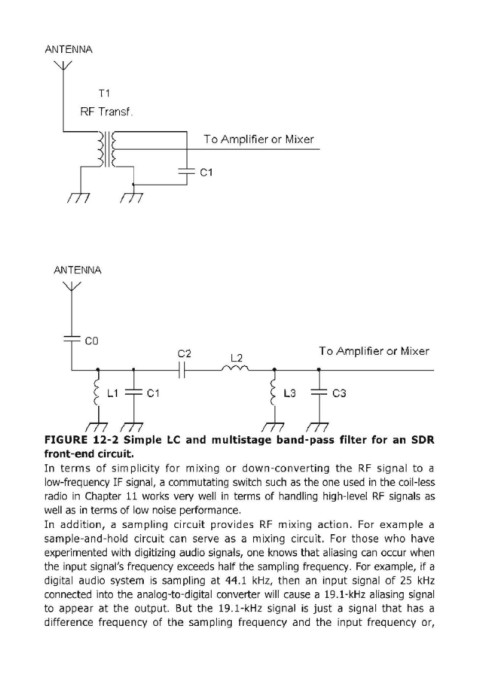
FIGURE 12-2 Simple Le and multistage band-pass filter for an SDR
front-end circuit.
In terms of simplicity for mixing or down-converting the RF signal to a
low-frequency IF signal, a commutating switch such as the one used in the coil-less
radio in Chapter 11 works very well in terms of handling high-level RF signals as
well as in terms of low noise performance.
In addition, a sampling circuit provides RF mixing action. For example a
sample-and-hold circuit can serve as a mixing circuit. For those who have
experimented with digitizing audio signals, one knows that aliasing can occur when
the input signal's frequency exceeds half the sampling frequency. For example, if a
digital audio system is sampling at 44.1 kHz, then an input signal of 25 kHz
connected into the analog-to-digital converter will cause a 19.1-kHz aliasing signal
to appear at the output. But the 19.1-kHz signal is just a signal that has a
difference frequency of the sampling frequency and the input frequency or,