
Page 178 - Build Your Own Transistor Radios a Hobbyists Guide to High-Performance and Low-Powered Radio Circuits
P. 178
alternatively stated, 44.1 kHz - 25 kHz = 19.1 kHz. So the sampling circuit can be
used as a mixer.
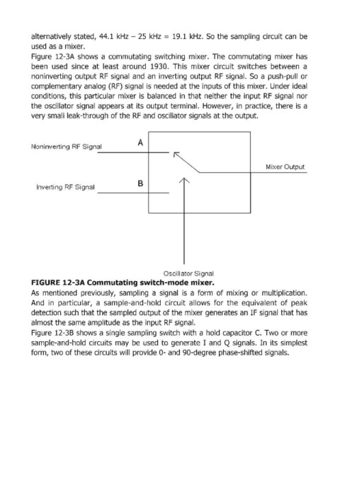
Figure 12-3A shows a commutating switching mixer. The com:mutating mixer has
been used since at least around 1930. This mixer circuit switches between a
non inverting output RF signal and an inverting output RF signal. So a push-pull or
complementary analog (RF) signal is needed at the inputs of this mixer. Under ideal
conditions, this particular mixer is balanced in that neither the input RF signali nor
the osciUator signal appears at its output terminal. However, in practice, there is a
very small leak-through of the RF and oscillator signals at the output.
A
Noninverting RF Sign al
Mixer Output
B / ~
Inverti ng RF Si gnal
Oscillator Signal
FIGURE 12-3A Com,mutating switch-mode mixer.
As mentioned previously, sampling a signal is a form of mixing or multiplication.
And in particular, a sample-and-hold circuit allows for the equivalent of peak
detection such that the sampled output of the mixer generates an IF signal that has
almost the same amplitude as the input RF signal.
Figure 12-38 shows a single sampling switch with a hold capacitor C. Two or m.ore
sample-and-hold circuits may be used to generate I and Q signals. In its simplest
form, two of these circuits will provide 0- and 90-degree phase-shifted signals.