
Page 179 - Build Your Own Transistor Radios a Hobbyists Guide to High-Performance and Low-Powered Radio Circuits
P. 179
Noninvert'n g RF Signal Mixer Output
/ "-
C
n
Oscillator Signal
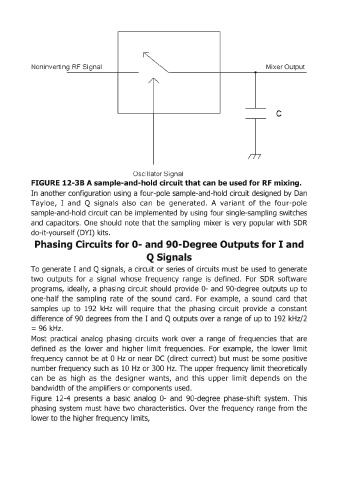
FIGURE 12-38 A sample-and-hold circuit that can be used for RF mixing.
In another configuration using a four-pole sample-and-hold circuit designed by Dan
Tayloe, I and Q signals also can be generated. A variant of the four-pole
sample-and-hold circuit can be implemented by using four single-sampling switches
and capacitors. One should note that the sampling mixer is very popular with SDR
do-it-yourself (DYI) kits.
Phasing Circuits for 0- an:d gO-Degree Outputs for I and
Q Signals
To generate I and Q signals, a circuit or series of circuits must be used to generate
two outputs for a signal whose frequency range is defined. For SDR software
programs, ideally, a phasing circuit should provide 0- and gO-degree outputs up to
one-half the sampling rate of the sound card. For example, a sound card that
samples up to 192 kHz will require that the phasing circuit provide a constant
difference of 90 degrees from the I and Q outputs over a range of up to 192 kHz/2
= 96 kHz.
Most practical analog phasing circuits work over a range of frequencies that are
defined as the lower and higher limit frequencies. For example, the lower limit
frequency cannot be at 0 Hz or near DC (direct currect) but must be some positive
number frequency such as 10 Hz or 300 Hz. The upper frequency limit theoretically
can be as high as the designer wants, and this upper limit depends on the
bandwidth of the amplifiers or components used.
Figure 12-4 presents a basic analog 0- and 90-degree phase-shift system. This
phasing system must have two characteristics. Over the frequency range from the
lower to the higher frequency limits,