Page 180 - Build Your Own Transistor Radios a Hobbyists Guide to High-Performance and Low-Powered Radio Circuits
P. 180

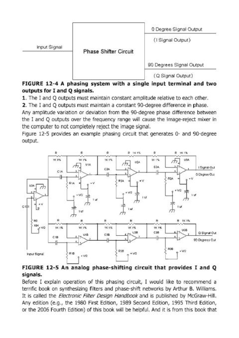
o Degree Signal Output


                                                                              ( I Signal  Output )
                   Input Signal
                                           Phase Shifter Circuit


                                                                           90 Degrees Signal Output

                                                                              ( Q Signal Output)
            FIGURE  12-4 A  phasing  system  with  a  single  input terminal  and  two

            outputs for I  and Q signals.
            1. The I and Q outputs must maintain constant amplitude relative to each  other.
            2. The I and Q outputs must maintain a constant 90-degree difference in  phase.
            Any  amplitude variation  or deviation  from  the  90-degree  phase  difference between
            the I  and  Q  outputs over the  frequency  range  will cause  the  image-reject mixer in

            the computer to not completely reject the image signal.
            Figure  12-5 provides  an example phasing  circuit  that generates  0- and  90-degree
            output.


                            R            R            R          R  lKl%      R         R  lKl%

                           lKl%         lKl%         lKl%     ~              lKl%      ~
                                                                                             USA
                                     ~               C2A            U2A       CSA       ,,.J        I Signal 0
                                            UlA
                              ClA                                                       , I •
                                                      "          ./                      v         o Degree Ou
                                                      "
                                        "                   R2A        . v           RSA   •   . v
                                    R1A   .,   +v                                          -
                UOAP                     ~                        L-                    .vn  ,~
                                                                . vn  ,;,;
                 ~>_L                  . vn                ~  J'~                   ~  J '"'
                  '1              ~        J '"'
            C =   "  +v                                                              J ,~
                   .!1                                       J'~
                                    J '"'
                  RO          R          R           R            R            R         R  lKl %
                  ""
                 _J  vn      lK , ,,    lKl%         lK 1%       lKl%         lK , %    8 ~ U38
                                                                     . ,
                                           Ul8       C28        I  f'I.... U28   C3B    • I .   ,   Q  Signal 0
                                                                  .
                           C18                ,                                           •
                                                                  •
                         YI                           "          ~                       ~        90 Degrees 0
                                                      "
                                        '"                                           R3B
               Input Signal         R18                     R28   i +VI2                 i + VI2
                                        r"VI2
                                                            .  .      .  .                 .
            FIGURE  12-5  An  analog  phase-shifting  circuit that  prOVides  I  and  Q
            signals.
            Before  I  explain  operation  of this  phasing  circuit,  I  would  like  to  recommend  a
            terrific  book on  synthesizing  filters  and phase-shift networks  by Arthur  B. Williams.

            It is called  the  Electronic Filter Design Handbook and  is published  by  McGraw-Hill.
            Any  edition  (e.g.,  the  1980  First Edition,  1989  Second  Edition,  1995  Third  Edition,
            or the 2006 Fourth Edition) of this  book will  be helpful.  And  it is from this book that
   175   176   177   178   179   180   181   182   183   184   185