
Page 185 - Build Your Own Transistor Radios a Hobbyists Guide to High-Performance and Low-Powered Radio Circuits
P. 185
Mult. I
-
"- X "- Filter I o Degree IF Sign al
-
/ /
I Channel Si gnal
/1"
Osci II ator Si gnal 0 Degree
Input Si gnal "
/
Mult. Q
"- X "- Filter Q 90 Degrees I F Si gnal
/ /
Q Channell Si gn al
l'
Oscillator Signal 90 Degrees
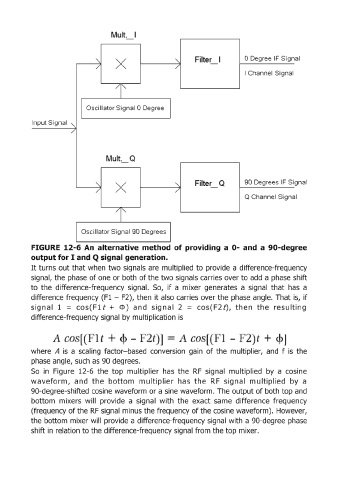
FIGURE 12-6 An alternative method of providing a 0- and a 90-degree
output for I and Q sig'nalgeneration.
It turns out that when two signals are multiplied to provide a difference-frequency
signal, the phase of one or both of the two signals carries over to add a phase shift
to the difference-frequency signal. So, if a mixer generates a signal that has a
difference frequency (F1 - F2), then it also carries over the phase angle. That is, if
i
s g n a I 1 = cos ( F 1 t + Cl» and si 9 n a I 2 = cos (F 2 t), th e nth e re suit in g
difference-frequency signal by multiplication is
l l l] - ·2 l J
where A is a scaling factor-based conversion gain of the multiplier, and f is the
phase angle, such as 90 degrees.
So in Figure 12-6 the top multiplier has the RF signal multiplied by a cosine
waveform, and the bottom mu ltiplier has the RF signal multiplied by a
90-degree-shifted cosine waveform or a sine waveform. The output of both top and
bottom mixers will provide a signal with the exact same difference frequency
(frequency of the RF signal minus the frequency of the cosine waveform). However,
the bottom mixer will provide a difference-frequency signal with a 90-degree phase
shift in relation to the difference-frequency signal from the top mixer.