
Page 189 - Build Your Own Transistor Radios a Hobbyists Guide to High-Performance and Low-Powered Radio Circuits
P. 189
• Tl: 42IF100, 42IFIIO, or 42IF300
• T2: 42IF100, 42IFIIO, or 42IF300 primary winding or 330-IJH variable inductor
• VC1: twin-gang variable capaCitor 270 pF and 270 pF
• Loop antenna to low-side tap of Tl
• Ul: 74HC04
• U2: UA733 or LM733 video differential amplifier
• U3: 74HC4053 or 74HCT4053
• U4, US, U6, U7: NE5532 or LM833
• US: LM78LOS
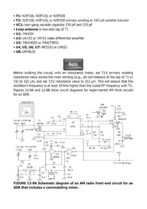
Before building the circuit, with an inductance meter, set Tl's primary winding
inductance value across the main winding (e.g., do not measure at the tap of Tl or
T2) to 322 IJH, and set T2's inductance value to 312 IJH. This will ensure that the
oscillator's frequency is at least 10 kHz higher than the tuned RF frequency with Tl.
Figures 12-SA and 12-88 show circuit diagrams for experimental AM front circuits
for an SDR.
Loop Antenna
U38
+5 C6
74HC4053 .01 ut
~Uf--Y ~
R6 4 .7
11 USA
C2
7
~Uf 12
T1 13
8
5 C3
R5 R4 R9
R1 12K +9 I .01 ut
--~~~ ,~------~ 12K 12K 1800 ToC8
Next Page
.oo'''l
.01 uf +5 +5 C7 --
VC1 Dsc VC1 Dsc Pad
R812K
270 pt 20 pt
+4 .5
1K
R3 To + 4.5 Next Page
U8
+ 9
78L05P +5 2M C9
.001 ut
C12 --T2
C11 r--1 J C10
T33 ut
T33 ut
rh rh 421FlOO .Q1 ut
FIGURE 12-SA Schematic diagram of an AM radio front-end circuit for an
SDR that includes a commutating mixer.