Page 190 - Build Your Own Transistor Radios a Hobbyists Guide to High-Performance and Low-Powered Radio Circuits
P. 190

R1i1         R13          R14      RI6   1K 1%   RH       R19   1K1%
                    C13
                    5 pt    1K 11%                   1K 1%                   l K1%
                                                                                             U7A
                                            U5A
                                                                                                   R20
                    R22
                                                                                                   100
                    220K
                                                                       +9
                              500 pr                                                                 C18
                                                       R15                                           33~T
                              R12                                             76.8K           C29
                                                     14K 1%     +4.5   C27
                               1620            C15                                         11ut
            R21                             l'                      11ur                           o Degree Out
            22K                                  u t            C26                    C28
                                        C25
                                                                                    11Uf             I Signal Out
                                                             l1ur
                                     l33ur
                              R23         R25        R26          R28          R29     R31   1K1%
                             1K1 %       lK1%
                                                                                                   R32
                                              7                                                    100
                                                                              500 pr
                                                     500 pt
                             500 pt                                                                  cn
                 Toe7                                                                                33utT
              of Previous Page   R24                    R27                     R30
                                          +4 .5                   +4.5                    +4 .5   90 Degrees Out
                              5900                     32.4K                   280K
                                                                                                   Q  Signal Out
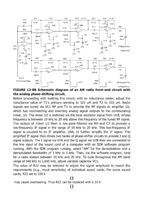
            FIGURE  12-88 Schematic diagram  of an  AM  radio front-end  circuit with
            the analog phase-shifting circuit.
            Before  proceeding  with  building  this  circuit,  with  an  inductance  meter,  adjust  the
            inductance  value  of Tl's  primary  winding  to  322  IJH  and  T2  to  310  IJH.  Radio

            signals  are  tuned  via  VCl  RF  and  Tl to  provide  the  RF  signals  to  amplifier  U2,
            which  has  noninverting  and  inverting  analog  signal  outputs  to  the  commutating
            mixer,  U3.  The  mixer U3  is switched via  the  local  oscillator signal from  U1B,  whose
            frequency is between  10 kHz to 20 kHz above the frequency of the tuned  RF signal.
            The  output  of mixer  U3  then  is  low-pass-filtered  via  R9  and  C7  to  provide  a

            low-frequency  IF  signal  in  the  range  of 10  kHz  to  20  kHz.  This  low-frequency  IF
            signal  is  coupled  to  an  IF  amplifier,  U4A,  to  further  amplify  the  IF signal.  The
            amplified IF signal then drives two banks of phase-shifter circuits to provide I  and Q
            signal  outputs. The I  signal via  U7 A and the Q signal via  U7B then are connected to
            the  line  input of the  sound  card  of a  computer  with  an  SDR  software  program
            running.  With  the  SDR  program  running,  select "AM" for  the  demodulation  and  a
            demodulated  bandwidth  of 3  kHz  to  5 kHz.  Then,  via  the  software  program,  tune

            for a radio  station  between  10  kHz  and  20  kHz.  To tune  throughout the AM  band
            range of 540  kHz to 1,600 kHz,  adjust variable capacitor VCl.
            The  value  of R22  may  be  selected  to  adjust  the  signal  amplitude  to  match  the
            requirements  (e.g.,  input  sensitivity)  of individual  sound  cards.  For  some  sound
            cards,  R22 set to 220 k


             may cause overloading. Thus R22  can  be replaced with a 22-k
   185   186   187   188   189   190   191   192   193   194   195