Page 187 - Build Your Own Transistor Radios a Hobbyists Guide to High-Performance and Low-Powered Radio Circuits
P. 187

I !rh     Loop Antenna


                        RF Filter Amp
                          VC1  RF

                           T1  U2
                                                                                                Computer

                                                                                                Audio Input
                     /~ ~1RF                   \                                    ISig.   ,
                                270 pI            Mixer and             I and Q
                                                                                              SDR Program
                                                  IF Amplifier        Phase Circuit           Image Reject
                                                                                    QSig.        Tuning
                                                   U3  U4               U5,U6,U7
                                                                                             AM/FMlSSB Det.
                                                                                              Audio Output
                          Oscillator
                          VC1  osc    -

                           T2  U1


                                 P
                     / 2701
                              VCl  Osc


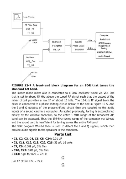
            FIGURE  12-7  A  front-end  block  diagram  for an  SDR  that tunes the
            standard AM  band.
            The  switch-mode  mixer  also  is  connected  to  a  local  oscillator  tuned  via  VC1  Osc
            that  is  set to about 15  kHz  above  the  tuned  RF  signal  such  that the output of the
            mixer  circuit  provides  a  low  IF  of about  15  kHz,  The  15-kHz  IF  signal  from  the
            mixer is connected to a phase-shifting circuit similar to the one in  Figure  12-5,  And

            the  I  and  Q outputs  of the  phase-shifting  circuit  then  are  coupled  to  the  audio
            inputs of a sound  card  in  a computer.  As  stated  previously,  tuning  is  accomplished
            mostly  by  the  variable  capacitor,  so  the  entire  1-MHz  range  of the  broadcast  AM
            band  can  be  accessed,  Thus the  192-kHz tuning  range  of the  computer via  Winrad
            and the sound card  is insufficient for tuning across the entire AM  band,

            The  SDR  program  Winrad  then  is  used  to  detect the  I  and  Q signals,  which  then
            provide audio signals to the speakers in the computer,
                                                     Parts List

            • Cl, C2, C3, C4, C6, CS, C24: 0,01  uF
            • CS, Cll, C12, C1S, C22, C2S: 33  ~F,  16 volts

            • C7, C9: 0,001  ~F, 5% film
            • C10, C23: 0,01  ~F, 5% film
            • C13:  5 pF for R22  =  220 k
                                                           n

            ; or 47  pF for R22  = 22 k
                                                           n
   182   183   184   185   186   187   188   189   190   191   192