
Page 186 - Build Your Own Transistor Radios a Hobbyists Guide to High-Performance and Low-Powered Radio Circuits
P. 186
The output of each m ixer then is connected to a filter to pass the
difference-frequency signal while removing other signals, such as a signal whose
frequency is the sum of the frequencies of the RF and cosine waveform. Thus the
outputs of the (identical) filters provide I (O-degree) and Q (gO-degree) signals,
which typically are low IF signals (e.g., < 100 kHz) for the SOR.
One advantage of multiplying mixers to generate I and Q signals is that there is
essentially no lower- or higher-limit frequency to worry about. So, if the frequency
ratio changes from 10: 1 to 1,000:1 in maintaining gO degrees of phase shift
between the two channels, the multiplier circuit in Figure 12-6 does not change,
whereas the phase-shifting circuit shown in Figure 12-5 increases in complexity.
One small downside to using switching mixers versus a phase-shifting network is
that the signal generator driving the switching mixer initially has to run at four
times the local oscilllator frequency. If an oscillator has a perfect square wave with
50 percent duty cycle, then the signal generator can run at twice the local oscillator
frequency. In order to synthesize a gO-degree phase-shifted version from the
generator, at least twice the local oscillator frequency is needed for a digital divider
circuit.
Examp'le Radio Circuits for Softwar'e-Defined Radios
For a first experiment in an SOR, an AM radio will be shown. It will contain some
circuits that were shown in previous chapters but will have a lower IF signal for
inputting to a computer's sound card.
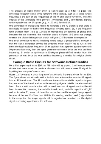
Figure 12-7 presents a block diagram of an AM radio front-end circuit for an SOR.
The figure shows an AM radio with a built-in loop antenna that couples RF signals
into an RF transformer. The RF transformer tunes with a variable capacitor to pass
frequencies of the tuned stations while removing signals outside the standard AM
band. Since a switch-mode mixer will be used, removal of signals outside the AM
band is essential. However, the variable tuned circuit, variable capacitor VC1_RF
and an inductor Tl, does not have the narrow bandwidth to reject image signals
because of the low IF of less than 20 kHz. Fortunately, via the I and Q signals fed
to the computer, the image signals will be rejected (or selected) via the digital
signal-processing algorithms in the software.