
Page 183 - Build Your Own Transistor Radios a Hobbyists Guide to High-Performance and Low-Powered Radio Circuits
P. 183
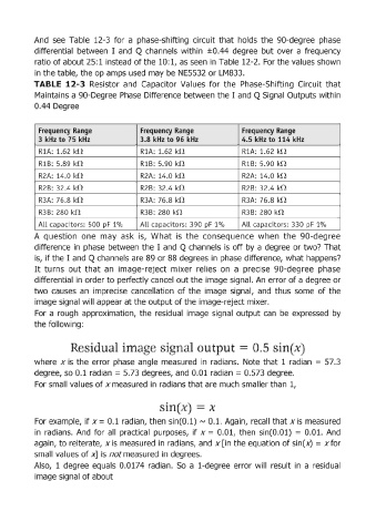
And  see  Table  12-3  for  a  phase-shifting  circuit  that  holds  the  gO-degree  phase

            differential  between  I  and  Q channels  within  ±0.44  degree  but over  a  frequency
            ratio of about 25:1 instead of the 10:1, as seen  in Table 12-2.  For the values shown
            in the table, the op amps used  may be  NE5532 or LM833.
            TABLE  12-3  Resistor  and  Capacitor  Values  for  the  Phase-Shifting  Circuit  that
            Maintains a gO-Degree  Phase  Difference between the I  and  Q Signal Outputs within
            0.44 Degree


             Frequency Range                  Frequency Range                 Frequency Range
             3 kHz to 75  kHz                 3.8 kHz to 96  kHz              4.5 kHz to 114 kHz

             RiA:  1.62 kn                    R1A: 1.62 kO                    R1A:  1.62 kO
             RiB: 5.89  kn                    RiB: 5.90 kO                    RiB:  5.90  kG
             R2A:  14.0 kn                    R2A: 14.0 kO                    R2A:  14.0 kO

             R2B:  32.4 kf!.                  R2B: 32.4 kO                    R2B:  32.4 kG
             R3A:  76.8 kO                    R3A:  76.8 k!1                  R3A:  76.8 kf!

             R3B:  280  kO                    R3B: 280  kO                    R3B:  280  kO
                                                                                                       0
             ALL  capacitors: 500  pF  1%     ALL  capacitors: 390  pF  1%    ALL  capacitors: 330  pF  1 /0
            A  question  one  may  ask  is,  What  is  the  consequence  when  the  90-degree
            difference  in phase  between  the I  and  Q channels is off by a degree or two? That

            is,  if the I  and  Q channels are 89 or 88 degrees in phase difference, what happens?
            It turns  out that  an  image-reject  mixer  relies  on  a  precise  gO-degree  phase
            differential in order to perfectly cancel  out the image signal. An  error of a degree or
            two  causes  an  imprecise  cancellation  of the  image  signal,  and  thus  some  of the
            image signal will appear at the output of the image-reject mixer.

            For  a rough  approximation,  the  residual  image  signal  output can  be  expressed  by
            the following:


                                                                                    .5

            where  x is  the  error  phase  angle  measured  in radians.  Note  that  1 radian  =  57.3
            degree, so 0.1 radian = 5.73 degrees, and  0.01  radian = 0.573 degree.

            For small!  values of x measured in radians that are much smaller than  1,
                                                      .
                                                      1

            For example, if x ==  0.1 radian, then  sinCO.'!)  rv  0.1.  Again,  recall  that x is measured
            in  radians. And  for all  practical  purposes,  if  x = 0.01,  then  sinCO.01)  = 0 .. 01.  And
            again,  to reiterate,  x is measured  in  radians,  and x [in the equation  of sin(x) = xfor
            small values of x]  is  notmeasured in  degrees.

            Also,  1 degree  equals 0.0174  radian.  So  a  1-degree  error  will  result  in  a  residual
            image signal of about