
Page 194 - Build Your Own Transistor Radios a Hobbyists Guide to High-Performance and Low-Powered Radio Circuits
P. 194
,,/ Long Wire Antenna
RF Filter Amp
T1 C3 -
01,02
Computer
, I Sig. Audio Input
Mixer and
/
/ " SDR Program
Amplifiers Image Reject
, Tuning
U4, U5,U6 OS;9· "
/ /
AM/FM/SSB Det.
Audio Output
Oscillator
0,90,180,270
I--
Phase Outputs
Y1 ,U2,U7
. . . .
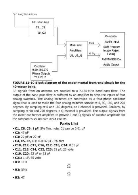
FIGURE 12-10 Block diagram of the experimental front-end circuit for the
40-meter band.
RF signals from an antenna are coupled to a 7.150-MHz band'pass filter. The
output of the band-pass filter is buffered by an amplifier to drive the inputs of four
analog switches. The analog switches are controlled by a four·phase oscillator
signal that is used to make the four analog switches sample at 0, 90, 180, and 270
degrees. By sampling at 0 and 180 degrees, an I channel is provided. Similarly, by
sampling at 90 and 270 degrees, a Q channel is provided. The output signals from
the mixer are further amplified to provide I and Q signals of suitable amplitude for
the computer's sound' card input circuits.
Parts List
• Cl, CB, C9: 1 ~F, 5% film, note: Cl can be 0.01 IJF
• C2: 47 pF
• C3: 22 pF or 27 pF
• C4, CS, C6, C7: 0.0047 ~F, 5% film
• C10, C12, C1S, C16, C17, C1B, C24: 0.01 ~F
• Cll, C13, C14, C22, C23: 33 ~F, 25 volts
• C19, C20: 22 pF or 33 pF
• C21: 1 ~F, 35 volts
• Rl: 11 k
n
• R2: 39 k
n
• R3: 47