
Page 193 - Build Your Own Transistor Radios a Hobbyists Guide to High-Performance and Low-Powered Radio Circuits
P. 193
R4w ------ 1----
~s.
1.77609
Fi e ----1-----
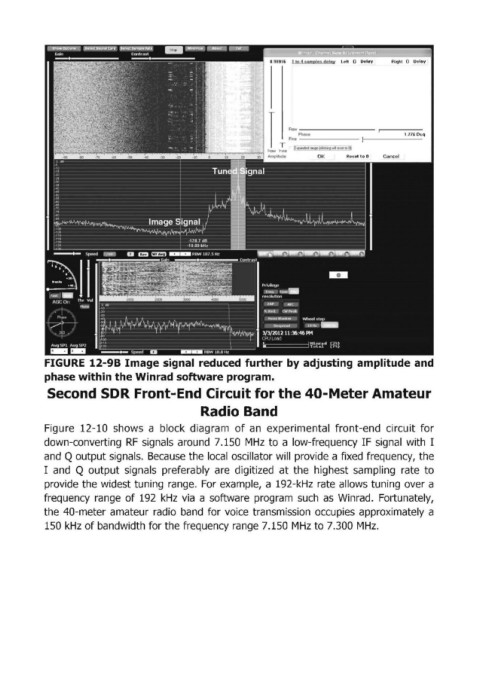
FIGURE 12-98 Image signal reduced further by adjusting amplitude and
phase within the Winrad software program.
Second SDR Front-End Circuit for the 40-Meter Amateur
Radio Band
Figure 12-10 shows a block diagram of an experimental front-end circuit for
down-converting RF signals around 7.150 MHz to a low-frequency IF signal with I
and Q output signals. Because the local oscillator will provide a fixed frequency, the
I and Q output signals preferably are digitized at the highest sampling rate to
provide the widest tuning range. For example, a 192-kHz rate allows tuning over a
frequency range of 192 kHz via a software program such as Winrad. Fortunately,
the 40-meter amateur radio band for voice transmission occupies approximately a
150 kHz of bandwidth for the frequency range 7.150 MHz to 7.300 MHz.