
Page 172 - Build Your Own Transistor Radios a Hobbyists Guide to High-Performance and Low-Powered Radio Circuits
P. 172
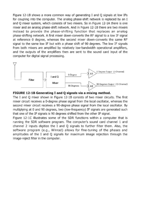
Figure  12-18 shows  a Imore  common  way  of generating  I  and  Q signals  at low IFs

            for coupling  into the computer.  The analog  phase-shift network is  replaced  by  an  I
            and  Q m,ixer system~,  which  consists of two mixers.  So  in  Figure  12-1A there is  one
            mixer and  an  analog  phase-shift network. And  in Figure 12-18 there are two mixers
            instead  to  provide  the  phase-shifting  function  that  replaces  an  analog
            phase-shifting  network. A first mlixer down-converts the RF  signal to a low IF signal
            at  reference  0  degree,  whereas  the  second  mixer  down-converts  the  same  RF
            signa:1 to the  same  low IF but with  a phase  shift of 90  degrees.  The  low IF signals

            from  both  mixers  are  amplified  by  relatively  low-bandwidth  operational  amplifiers,
            and  the  outputs  of the  amplifiers  then  are  sent  to  the  sound  card  input  of the
            computer for digital signal  processing.


                                                                                   o Degree Output  ( I Channel)
                                                           o Degree
                                            land Q
                         Filter
                                             Mixer                                 90 Degrees Output  (Q Channel)
                                                           90  Degrees  L-----------,1I  A2


            FIGURE 12-18 Generating I  and Q signals via a mixing method.
            The  I  and  Q mixer  shown  in  Figure  12-1B  consists  of two  mixer circuits.  The  first
            mixer circuit receives a O-degree phase signal from the local  oscillator,  whereas the
            second  mixer circuit receives a 90-degree phase  signal  from  the local  oscillator.  By

            multiplying  at 0 and  90 degrees,  two (Iow-frequency) IF signals are generated such
            that one of the IF signals is 90 degrees shifted from the other IF signal.
            Figure  12-1C  illustrates  some  of the  5DR  functions  within  a  computer  that  is
            running  the  SDR  software  program.  The  computer's  sound  card  channel  1  and
            channel  2  inputs  digitize  the  I  and  Q  signals  to  further  filter  them.  Also,  the
            software  program  (e.9.,  Winrad)  allows  for  fine-tuning  of the  phases  and

            amplitudes  of the  I  and  Q signals  for  maximum  image  rejection  through  the
            image-reject filter in the computer.