
Page 171 - Build Your Own Transistor Radios a Hobbyists Guide to High-Performance and Low-Powered Radio Circuits
P. 171
Let's take an example of a theoretical broadcast AM radio system in which there is
no tuned RF filter prior to mixing. Recall from Chapter 8 that superheterodyne
radios always use a tuned RF filter via variable capacitor VCl_RF to pass the radio
station's signal to the mixer or converter circuit. And recall that the local oscillators
or converter circuits in Chapter 8 have large oscillator signals that purposely cause
distortion in order to provide a multiplying effect in the mixer or converter circuits.
This distortion owing to the large amplitude of the oscillator signal also results in
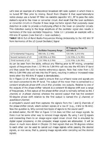
harmonics of the local oscillator frequency. Table 12-1 provides an example with a
455-kHz IF system (note that LO = local oscillator).
TABLE 12-1 Out-of-Band Radio-Frequencies Mixing Undesirably to the 455 kHz IF
from Harmonics of the LO (Local Oscillator) Signal
RF Frequency Range for
Oscillator Frequency Range 455-kHz IF
LO fu ndamental frequency 990 kHz-2.1 MHz 535 kHz- l,645 kHz
Second harmonic of LO 1.98 MHz- 4.2 MHz 1.52 MHz- 3.74 MHz
Third harmonic of LO 2.97 MHz- 6.3 MHz 2.51 MHz- 5.84 MHz
..
As can be seen from the table, without any filtenng pnor to RF mixing, unwanted
signals of frequencies from 1.52 MHz to 5.84 MHz will mix into the 455-kHz IF band
and thus cause the radio to receive extraneous signals. Note that noise from 1.52
MHz to 5.84 MHz also will mix into the IF band, resulting in extra or increased noise
levels when the 455-kHz IF signal is demodulated.
So in Figure 12-1A a filter is used to ensure that out-of-band noise and signals are
not down-converted to the IF band. The output of the mixer then is connected to a
constant-amplitude phase-shift circuit that provides two outputs. Relative to one of
the outputs of the phase-shifter network is a constant 90-degree shift over a range
of frequencies. A first output of the phase-shifter circuit is normally defined as the I
channel, or in-phase channel, whereas the second output that has the constant
90-degree phase shift relative to the first output is named the Q channel, or
quadrature channel.
A computer's sound card then captures the signals from the I and Q channels of
the phase-shifter circuit, which contain signals of a low IF (e.g., 3 kHz to 96 kHz).
Now the question is, Why connect two types of signals to the sound card?
As stated earlier, the RF filter in Figure 12-1A does not filter out image signals. So
there must be some other way to remove image signals. By using I and Q signals
and connecting them to an image-signa I-reject mixer circuit that is emulated by
digital signal processing in the computer, image signals are attenuated. It will be
shown in much more detail in Chapter 21 that signals that are 90 degrees relative
to each other can be used to cancel out image signals while passing the desired
signals, or vice versa, that is, passing image signals while canceling out the desired
signals.