
Page 160 - Build Your Own Transistor Radios a Hobbyists Guide to High-Performance and Low-Powered Radio Circuits
P. 160
+ 9
U1A
LME49720
co
C1
3
2
CA
R1
RA
L =CAxAAxRB
J 0.01 ut
R2
RB
L=CAxAAxRB
L
CAx RAx R8
R2
RB
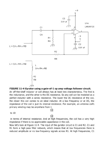
FIGURE 11-4 Gyrator using a gain-of-1 op a,mip voltage follower circuit.
An off-the-shelf inductor or coil always has at least two characteristics. The first is
the inductance, and the other is the DC resistance. So any coil can be modeled as a
perfect inductor with a series resistance. The lower the DC resistance of the coil,
the closer this coil comes to an ideal inductor. At a low frequency or at DC, the
impedance of the coil is just its internal resistance. For example, an antenna coil's
primary winding may be anywhere from 1
to 10
in terms of internal resistance. And at high frequencies, the coil has a very high
impedance if there is no appreciable capacitance in the coil.
Now let's look at Figure 11-4. The input of the gyrator circuit is Cl and R2. Cl and
R1 form a high-pass filter network, which means that at low frequencies there is
reduced amplitude or no low-frequency signals across Rl. At high frequencies, Cl