
Page 157 - Build Your Own Transistor Radios a Hobbyists Guide to High-Performance and Low-Powered Radio Circuits
P. 157
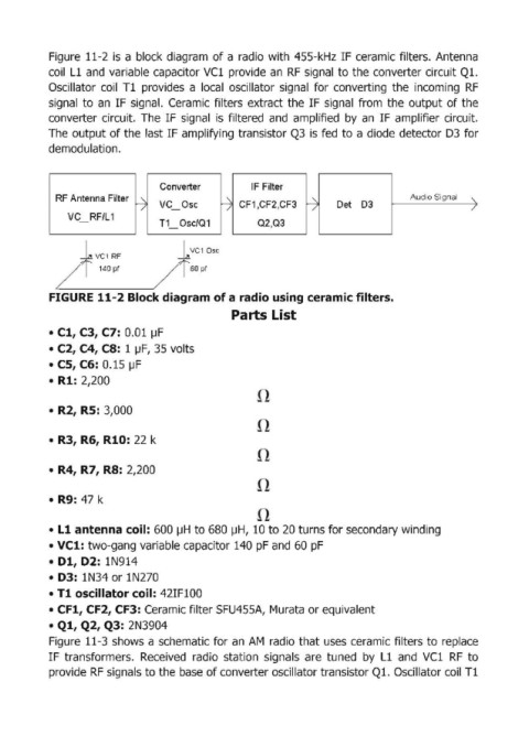
Figure  11-2  is  a block  diagram  of a radio  with  455-kHz IF ceramic filters.  Antenna

            coil  Ll and  variable capacitor VCl  provide  an  RF  signal  to the converter circuit Q1.
            Oscillator  coil  Tl  provides  a  local  oscillator  signal  for  converting  the  incoming  RF
            signal  to  an  IF signal.  Ceramic  filters  extract the  IF signal  from  the  output of the
            converter  circuit.  The  IF  signal  is  filtered  and  amplified  by  an  IF amplifier  circuit.
            The  output of the  last IF amplifying transistor Q3  is fed  to a diode detector D3  for
            demodulation ..


                                     Converter            IF Filter
              RF Ant1enna Filter                                                              Audio Signal   \.
                                ~    VC  Dsc       -j  CF1 ,CF2,CF3   -j:    Det  03                        /
                VC  RF/L 1
                                     T1  Dsc/Q1            Q2,Q3         I
                                                                         I

                                            VC10SC
                   +                     +
                      VC1  RF
              /        140pf        /       60pf

            FIGURE 11-2 Block diagram of a radio using ceramic filters.

                                                     Parts list
            • Cl, C3, C7: 0.01  lJF

            • C2, C4, CS:  1 lJF,  35 volts
            • CS, C6: 0.15  lJF
            •  Rl: 2,200


            •  R2, RS:  3,000


            •  R3, R6, RlO: 22  k


            • R4, R7, RS:  2,200


            •  R9: 47 k


            •  L1 antenna coil: 600 I-IH  to 680 I-IH,  10 to 20 turns for secondary winding
            • VCl: two-gang variable capacitor 140 pF and 60 pF

            •  Dl, D2:  IN914
            •  D3:  IN34 or IN270
            • Tl oscillator coil: 42IF100

            • CFl, CF2, CF3: Ceramic filter SFU455A,  Murata or equivalent
            • Ql, Q2, Q3: 2N3904
            Figure  11-3 shows  a schematic for an  AM  radio that uses ceramic filters to  replace
            IF  transformers.  Received  radio  station  signals  are  tuned  by  Ll  and  VCl  RF  to
            provide RF signals to the base of converter oscillator transistor Ql. Oscillator coil Tt