
Page 213 - Build Your Own Transistor Radios a Hobbyists Guide to High-Performance and Low-Powered Radio Circuits
P. 213
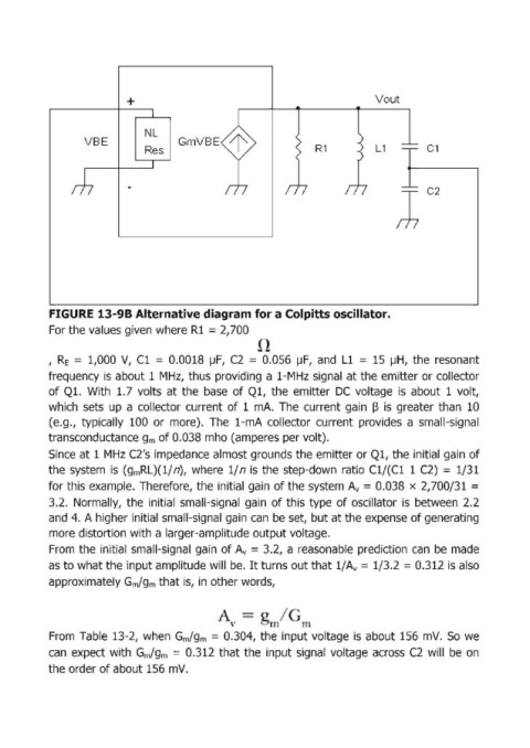
+                                                       Vout


                                  NL
                    VBE
                                  Res                                   R1            L1         C1


            FIGURE 13-98 Alternative diagram for a Colpitts oscillator.
            For the values given where RI = 2,700


            ,  RE  =  1,000  V,  Cl  =  0.0018  ~F, C2  =  0.056  ~F, and  Ll  =  15  ~H, the  resonant
            frequency is  about 1 MHz,  thus providing a 1-MHz signal' at the emitter or collector

            of Q1.  With  1.7  volts  at the  base  of Ql,  the  emitter  DC  voltage  is  about  1 volt,
            which  sets  up  a collector  current  of 1 mA.  The  current  gain  ~ is  greater than  10
            (e.g.,  typically  100  or  more).  The  1-mA  collector  current  provides  a  small-signal
            transconductance gm  of 0.038 mho (amperes per volt).

            Since at 1 ,MHz C2's impedance almost grounds the emitter or Ql, the initiall gain of
            the system  is  (gmRL)(l/ n),  where  1/ n is  the step-down  ratio  Cl/(Cl  1 C2)  = 1/31
            for this example.  Therefore, the initial gain  of the system  Av  =  0.038  x  2,700/31  =
            3.2.  Normally,  the  initial  small-signal  gain  of this  type  of oscillator  is  between  2.2
            and 4.  A higher initial small-signal  gain can  be set,  but at the expense of generating

            more distortion with a larger-amplitude output voltage.
            From  the  initial  small-signal  gain  of Av  =  3.2,  a reasonable  prediction  can  be  made
            as to what the input amplitude will  be.  It turns out that l/Av = 1/3.2 = 0.312 is also

            approximately Gm/gm  that is,  in other words,


                                                                /

            From  Table  13-2,  when  Gm/gm  = 0.304,  the  input voltage  is  about 156  mV.  So  we

            can  expect  with  Gm/gm  = 0.312  that the  input signal  voltage  across  C2  will  be  on
            the order of about 156 mV.